
User Manual
Page 3
... harmful interference to part 15 of this equipment in a residential area is operated in which case the user will be required to operate the equipment. power cord, if any, must be used in accordance with the emission limits.
... harmful interference to part 15 of this equipment in a residential area is operated in which case the user will be required to operate the equipment. power cord, if any, must be used in accordance with the emission limits.
User Manual
Page 4
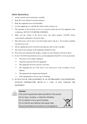
...any of the following situations arises, get it work well or you cannot get the equipment checked by a service personnel: • The power cord or plug is damaged • Liquid has penetrated into the opening. Never pour any liquid into the equipment • The equipment has...Lay this product. The openings on the enclosure are for air convection hence protects the equipment from humidity. 4. Do not place anything over the power cord. 8. Liquid can cause damage or electrical shock. 11. Caution: Only use the appropriate battery specified for future reference. 3. Do not discard...
...any of the following situations arises, get it work well or you cannot get the equipment checked by a service personnel: • The power cord or plug is damaged • Liquid has penetrated into the opening. Never pour any liquid into the equipment • The equipment has...Lay this product. The openings on the enclosure are for air convection hence protects the equipment from humidity. 4. Do not place anything over the power cord. 8. Liquid can cause damage or electrical shock. 11. Caution: Only use the appropriate battery specified for future reference. 3. Do not discard...

User Manual
Page 6
... 1 Mainboard Specifications 2 Mainboard Layout 4 Back Panel Layout 5 Back Panel Ports 6 Slots 6 Onboard Connectors 7 Onboard Jumpers 7 Chapter 2 9 Installation 9 CPU 10 Memory Module Installation 14 Connecting the Power Supply 17 Back Panel Ports 19 Connectors 23 Jumpers 38 Slots 41 Chapter 3 43 BIOS Setup 43 Entering Setup 44 Control Keys 45 Navigating the...
... 1 Mainboard Specifications 2 Mainboard Layout 4 Back Panel Layout 5 Back Panel Ports 6 Slots 6 Onboard Connectors 7 Onboard Jumpers 7 Chapter 2 9 Installation 9 CPU 10 Memory Module Installation 14 Connecting the Power Supply 17 Back Panel Ports 19 Connectors 23 Jumpers 38 Slots 41 Chapter 3 43 BIOS Setup 43 Entering Setup 44 Control Keys 45 Navigating the...

User Manual
Page 7
Integrated Peripherals 59 Super IO Device 61 Power Management Setup 63 Peripheral Activities 65 IRQs Activities 68 PNP/PCI Configurations 69 IRQ Resources 71 PC Health Status 72 Frequency / Voltage Control 73 Load Fail-Safe Defaults 76 Load Optimized Defaults 77 Set Supervisor / User Password 78 Save & Exit Setup 80 Exit Without Saving 81 Chapter 4 83 Driver Installation 83 Driver Utilities 84 CD Content 86 iii
Integrated Peripherals 59 Super IO Device 61 Power Management Setup 63 Peripheral Activities 65 IRQs Activities 68 PNP/PCI Configurations 69 IRQ Resources 71 PC Health Status 72 Frequency / Voltage Control 73 Load Fail-Safe Defaults 76 Load Optimized Defaults 77 Set Supervisor / User Password 78 Save & Exit Setup 80 Exit Without Saving 81 Chapter 4 83 Driver Installation 83 Driver Utilities 84 CD Content 86 iii

User Manual
Page 9
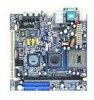
CHAPTER 1 Specifications The ultra-compact and highly integrated VIA EPIA-SP uses the MiniITX mainboard form-factor developed by VIA Technologies, Inc. The mainboard enables the creation of an exciting new generation of small, ergonomic, innovative and affordable embedded systems. Through a high level of integration, the Mini-ITX occupy 66% of the size of ultra-low power consumption, cool and quite operation. 1 The mainboard comes with an embedded VIA Processor, boasting of FlexATX mainboard form factor. as part of the company's open industry-wide total connectivity initiative.
CHAPTER 1 Specifications The ultra-compact and highly integrated VIA EPIA-SP uses the MiniITX mainboard form-factor developed by VIA Technologies, Inc. The mainboard enables the creation of an exciting new generation of small, ergonomic, innovative and affordable embedded systems. Through a high level of integration, the Mini-ITX occupy 66% of the size of ultra-low power consumption, cool and quite operation. 1 The mainboard comes with an embedded VIA Processor, boasting of FlexATX mainboard form factor. as part of the company's open industry-wide total connectivity initiative.

User Manual
Page 11
...; 2 x Fan connectors (CPU Fan and System Fan) • 1 x +12V power connector • 1 x SMBus connector • 1 x LVDS (function to be supported w/ an additional daughter card) • 1 x WP pin header BIOS • • Award BIOS with 4/8Mbit flash memory capacity ACPI2.0, SMBIOS2.1 and DMI2.2 Form Factor • Mini-ITX (6 layers) • 17 cm X 17 cm 3
...; 2 x Fan connectors (CPU Fan and System Fan) • 1 x +12V power connector • 1 x SMBus connector • 1 x LVDS (function to be supported w/ an additional daughter card) • 1 x WP pin header BIOS • • Award BIOS with 4/8Mbit flash memory capacity ACPI2.0, SMBIOS2.1 and DMI2.2 Form Factor • Mini-ITX (6 layers) • 17 cm X 17 cm 3

User Manual
Page 15
... +12V_CONN 1394_1 ATXPWR CD_IN COM 2 CPUFAN FIR F_AUDIO F_PANEL IDE 1-2 KBMS Header LPT LVDS SATA1 and 2 SMBus_Header SYSFAN USB 3-4/5-6/7-8 VIP_2 WOL Description 12V Power connector IEEE 1394 connector Power cable connector Onboard CD audio cable connector COM port 2 connector CPU fan connector Fast Infrared Radiation connector Front Audio connector Front panel connector...
... +12V_CONN 1394_1 ATXPWR CD_IN COM 2 CPUFAN FIR F_AUDIO F_PANEL IDE 1-2 KBMS Header LPT LVDS SATA1 and 2 SMBus_Header SYSFAN USB 3-4/5-6/7-8 VIP_2 WOL Description 12V Power connector IEEE 1394 connector Power cable connector Onboard CD audio cable connector COM port 2 connector CPU fan connector Fast Infrared Radiation connector Front Audio connector Front panel connector...

User Manual
Page 18
Chapter 2 CPU The VIA C3 E-Series Processor The VIA EPIA-SP Mini-ITX mainboard includes an embedded VIA C3 or Eden Processor. The VIA C3 Processor provides ultra-low power consumption and advanced thermal dissipation properties. Ensure that the CPU fan is correctly installed as shown. 10 The VIA C3 Processor requires heatsink and a CPU fan to provide sufficient cooling.
Chapter 2 CPU The VIA C3 E-Series Processor The VIA EPIA-SP Mini-ITX mainboard includes an embedded VIA C3 or Eden Processor. The VIA C3 Processor provides ultra-low power consumption and advanced thermal dissipation properties. Ensure that the CPU fan is correctly installed as shown. 10 The VIA C3 Processor requires heatsink and a CPU fan to provide sufficient cooling.

User Manual
Page 19
Any attempt to operate beyond product specifications. 11 We do not guarantee the damage or risks caused by inadequate operation or beyond product specifications is not designed to support overclocking. Installation The VIA Eden Processor Providing ultra-low power consumption and advanced thermal dissipation properties, the VIA Eden Processor features a fanless design. The VIA Eden Processor requires only a heatsink as shown. Caution: This mainboard is not recommended.
Any attempt to operate beyond product specifications. 11 We do not guarantee the damage or risks caused by inadequate operation or beyond product specifications is not designed to support overclocking. Installation The VIA Eden Processor Providing ultra-low power consumption and advanced thermal dissipation properties, the VIA Eden Processor features a fanless design. The VIA Eden Processor requires only a heatsink as shown. Caution: This mainboard is not recommended.

User Manual
Page 20
Chapter 2 CPU Fan and System Fan: CPUFAN and SYSFAN The CPUFAN (CPU fan) and SYSFAN (system fan) run on +12V and maintain system cooling. When connecting the wire to the connectors, always be aware that the red wire is Ground and should be connected to support fan monitoring except for +12V_CONN. 1 +12V_CONN 1 CPUFAN 1 SYSFAN C3TM Processor CN400 VT8237R 12 The CPU system and power fan connectors have sensors to GND. The black wire is the Positive and should always be connected to the +12V.
Chapter 2 CPU Fan and System Fan: CPUFAN and SYSFAN The CPUFAN (CPU fan) and SYSFAN (system fan) run on +12V and maintain system cooling. When connecting the wire to the connectors, always be aware that the red wire is Ground and should be connected to support fan monitoring except for +12V_CONN. 1 +12V_CONN 1 CPUFAN 1 SYSFAN C3TM Processor CN400 VT8237R 12 The CPU system and power fan connectors have sensors to GND. The black wire is the Positive and should always be connected to the +12V.

User Manual
Page 21
Installation +12V Power Connector This 12V power connector is used to provide additional +12V power to the rest of the system. Pin Signal 1 +12V 2 GND 1 +12V_CONN 13
Installation +12V Power Connector This 12V power connector is used to provide additional +12V power to the rest of the system. Pin Signal 1 +12V 2 GND 1 +12V_CONN 13

User Manual
Page 25
Then push down the plug firmly into the connector. 1 ATXPWR C3TM Processor 17 CN400 VT8237R Installation CONNECTING THE POWER SUPPLY The VIA EPIA-SP Mini-ITX mainboard supports a conventional ATX power supply for the power system. ATX 20-Pin Power Connector To connect the ATX power supply, make sure that all components are aligned. Before inserting the power supply connector, always make sure the power plug is inserted in the proper orientation and the pins are installed correctly to ensure that no damage will be caused.
Then push down the plug firmly into the connector. 1 ATXPWR C3TM Processor 17 CN400 VT8237R Installation CONNECTING THE POWER SUPPLY The VIA EPIA-SP Mini-ITX mainboard supports a conventional ATX power supply for the power system. ATX 20-Pin Power Connector To connect the ATX power supply, make sure that all components are aligned. Before inserting the power supply connector, always make sure the power plug is inserted in the proper orientation and the pins are installed correctly to ensure that no damage will be caused.

User Manual
Page 26
Chapter 2 ATX 20 Pin Power Connector Pin Signal Pin 1 +3.3V 11 2 +3.3V 12 3 GND 13 4 +5V 14 5 GND 15 6 +5V 16 7 GND 17 8 Power Good 18 9 +5V Standby 19 10 +12V 20 Signal +3.3V -12V GND Power Supply On GND GND GND NC +5V +5V 18
Chapter 2 ATX 20 Pin Power Connector Pin Signal Pin 1 +3.3V 11 2 +3.3V 12 3 GND 13 4 +5V 14 5 GND 15 6 +5V 16 7 GND 17 8 Power Good 18 9 +5V Standby 19 10 +12V 20 Signal +3.3V -12V GND Power Supply On GND GND GND NC +5V +5V 18

User Manual
Page 32
Chapter 2 If two drives are connected to a single cable, the jumper on Modules (DOM). Both IDE1 and IDE2 have a 20th pin included. Refer to slave mode. The 20th pin was added to provide extra voltage to power 40-pin Disk-on the second drive must use IDE cables that do not block the 20th pin. 24 See voltage selector: J1 on page 38 and 40. You must be set to the drive documentation supplied by the vendor for the jumper settings.
Chapter 2 If two drives are connected to a single cable, the jumper on Modules (DOM). Both IDE1 and IDE2 have a 20th pin included. Refer to slave mode. The 20th pin was added to provide extra voltage to power 40-pin Disk-on the second drive must use IDE cables that do not block the 20th pin. 24 See voltage selector: J1 on page 38 and 40. You must be set to the drive documentation supplied by the vendor for the jumper settings.

User Manual
Page 34
Chapter 2 Case Connector: F_PANEL The F_PANEL pin header allows you to connect the power switch, reset switch, power LED, HDD LED and the case speaker. C3TM Processor CN400 VT8237R Case Connector: F_PANEL Pin Signal Pin 1 +5VDUAL 2 3 +5VDUAL 4 5 -PLED 6 7 +5V 8 9 NC 10 11 NC 12 13 SPEAK 14 15 Key 16 Signal +5V HD_LED PW_BN GND RST_SW GND +5V -SLEEP_LED 1 F_PANEL 26
Chapter 2 Case Connector: F_PANEL The F_PANEL pin header allows you to connect the power switch, reset switch, power LED, HDD LED and the case speaker. C3TM Processor CN400 VT8237R Case Connector: F_PANEL Pin Signal Pin 1 +5VDUAL 2 3 +5VDUAL 4 5 -PLED 6 7 +5V 8 9 NC 10 11 NC 12 13 SPEAK 14 15 Key 16 Signal +5V HD_LED PW_BN GND RST_SW GND +5V -SLEEP_LED 1 F_PANEL 26

User Manual
Page 35
... If the system is used to this pin. Avoid turning the power off . Connect the HDD LED from the system case to a 2-pin power button switch. Installation Power Switch (PW_BN) Connect to this pin. 27 Pressing this button will turn the system power on . Avoid rebooting the system, if the HDD is on or... HDD LED shows the activity of a hard disk drive. Connect the reset switch from the system case to reboot the system rather than turning the power ON/OFF. Power LED (-PLED) The LED will blink. Suspend To RAM) state, the LED will light when the system is still working.
... If the system is used to this pin. Avoid turning the power off . Connect the HDD LED from the system case to a 2-pin power button switch. Installation Power Switch (PW_BN) Connect to this pin. 27 Pressing this button will turn the system power on . Avoid rebooting the system, if the HDD is on or... HDD LED shows the activity of a hard disk drive. Connect the reset switch from the system case to reboot the system rather than turning the power ON/OFF. Power LED (-PLED) The LED will blink. Suspend To RAM) state, the LED will light when the system is still working.

User Manual
Page 39
C3TM Processor CN400 1 COM2 1 CD_IN 1 1394 VT8237R 1 WOL Wake-On LAN connector: WOL Pin Signal 1 +5VDUAL 2 GND 3 WOL IN Description VCC Ground Wake on LAN Input 31 Installation Wake-On LAN: WOL This connector allows you to connect a network card with the Wake-On LAN function. The connector will unplug the power cord or turn off the power button manually. Please note that the function of ACPI WOL may be disabled when users will power up the system when a signal is received through the network card.
C3TM Processor CN400 1 COM2 1 CD_IN 1 1394 VT8237R 1 WOL Wake-On LAN connector: WOL Pin Signal 1 +5VDUAL 2 GND 3 WOL IN Description VCC Ground Wake on LAN Input 31 Installation Wake-On LAN: WOL This connector allows you to connect a network card with the Wake-On LAN function. The connector will unplug the power cord or turn off the power button manually. Please note that the function of ACPI WOL may be disabled when users will power up the system when a signal is received through the network card.

User Manual
Page 42
Pin Signal Description 1 FRNMIC Front panel microphone input 2 AGND Ground used by analog audio circuit 3 MIC_BIAS Microphone power 4 +5V AUDIO VCC used by analog audio circuit 5 LINE_OUT_R Right channel audio signal 6 NEXT_R Right channel audio signal return 7 NC No connection ...Line-Out connector on the back panel will not function. 34 Chapter 2 Front Panel Audio Connector: F_AUDIO This is an interface for the VIA front panel audio cable that allow convenient connection and control of audio devices. By default, the pins labeled LINE_OUT_R/NEXT_R and the pins ...
Pin Signal Description 1 FRNMIC Front panel microphone input 2 AGND Ground used by analog audio circuit 3 MIC_BIAS Microphone power 4 +5V AUDIO VCC used by analog audio circuit 5 LINE_OUT_R Right channel audio signal 6 NEXT_R Right channel audio signal return 7 NC No connection ...Line-Out connector on the back panel will not function. 34 Chapter 2 Front Panel Audio Connector: F_AUDIO This is an interface for the VIA front panel audio cable that allow convenient connection and control of audio devices. By default, the pins labeled LINE_OUT_R/NEXT_R and the pins ...

User Manual
Page 47
... by erasing the CMOS RTC RAM data. Replace the battery. 5. it will cause system boot failure. Turn OFF the computer and unplug the power cord. 2. Plug the power cord and turn ON the computer. 6. Hold down the key during the boot process and enter BIOS setup to clear the Real Time Clock... jumper allows you to re-enter data. Avoid clearing the CMOS while the system is on CLEAR_CMOS jumper default position. The onboard 1 1 button cell battery powers the RAM data in CMOS.
... by erasing the CMOS RTC RAM data. Replace the battery. 5. it will cause system boot failure. Turn OFF the computer and unplug the power cord. 2. Plug the power cord and turn ON the computer. 6. Hold down the key during the boot process and enter BIOS setup to clear the Real Time Clock... jumper allows you to re-enter data. Avoid clearing the CMOS while the system is on CLEAR_CMOS jumper default position. The onboard 1 1 button cell battery powers the RAM data in CMOS.

User Manual
Page 49
C3TM Processor PCI Slot 41 VT8237R Read the documentation for the expansion card if any changes to insert PCI expansion card. When adding or removing expansion card, unplug first the power supply. CN400 Installation SLOTS Peripheral Component Interconnect: PCI The PCI slot allows you to the system are necessary.
C3TM Processor PCI Slot 41 VT8237R Read the documentation for the expansion card if any changes to insert PCI expansion card. When adding or removing expansion card, unplug first the power supply. CN400 Installation SLOTS Peripheral Component Interconnect: PCI The PCI slot allows you to the system are necessary.