
User Manual
Page 1
User's Manual EPIA-ML Mini-ITX Mainboard Version 1.0 July 7, 2004
User's Manual EPIA-ML Mini-ITX Mainboard Version 1.0 July 7, 2004
User Manual
Page 6
Table of Contents Chapter 1: Specifications 1-1 Mainboard Specifications 1-2 Mainboard Layout 1-4 Back Panel Ports 1-5 Slots 1-5 Onboard Connectors and Jumpers 1-6 Chapter 2: Installation 2-1 CPU Installation 2-2 Memory Module Installation 2-4 Connecting the Power Supply 2-6 Back Panel Ports 2-7 Connectors 2-12 ...
Table of Contents Chapter 1: Specifications 1-1 Mainboard Specifications 1-2 Mainboard Layout 1-4 Back Panel Ports 1-5 Slots 1-5 Onboard Connectors and Jumpers 1-6 Chapter 2: Installation 2-1 CPU Installation 2-2 Memory Module Installation 2-4 Connecting the Power Supply 2-6 Back Panel Ports 2-7 Connectors 2-12 ...
User Manual
Page 7
... factor. This chapter includes the following sections: Mainboard Specifications 1-2 Mainboard Layout 1-4 Back Panel Ports 1-5 Slots 1-5 Connectors / Jumpers 1-6 1-1 The mainboard comes with an embedded VIA Processor, boasting ultra low power consumption and cool, quiet operation. The mainboard enables the creation of an exciting new generation ...'s open industry-wide total connectivity initiative. Chapter Specifications The ultra-compact and highly intergrated VIA EPIA-ML Mini-ITX Mainboard is the smallest form factor mainboard specification available today, developed by...
... factor. This chapter includes the following sections: Mainboard Specifications 1-2 Mainboard Layout 1-4 Back Panel Ports 1-5 Slots 1-5 Connectors / Jumpers 1-6 1-1 The mainboard comes with an embedded VIA Processor, boasting ultra low power consumption and cool, quiet operation. The mainboard enables the creation of an exciting new generation ...'s open industry-wide total connectivity initiative. Chapter Specifications The ultra-compact and highly intergrated VIA EPIA-ML Mini-ITX Mainboard is the smallest form factor mainboard specification available today, developed by...

User Manual
Page 8
Chapter 1 Mainboard Specifications CPU • VIA C3 / EDEN EBGA Processor (on board) • Enhanced Ball Grid Array Package (EBGA) • Internal L1 128KB and L2 64KB cache memory Chipset • VIA CLE266 North Bridge • VT8235 South Bridge Graphics • Integrated UniChrome graphics with Smart 5.1 ...8226; Up to 1GB memory size PCI Bus & IDE • 1 PCI slot • 2 X UltraDMA 66 / 100 / 133 Connector LAN • VIA VT6103 10 / 100 Base-T Ethernet PHY USB • USB v2.0 / v1.1 1-2 switched to 6-channel output during 6-channel operations with MPEG-2 accelerator Audio ...
Chapter 1 Mainboard Specifications CPU • VIA C3 / EDEN EBGA Processor (on board) • Enhanced Ball Grid Array Package (EBGA) • Internal L1 128KB and L2 64KB cache memory Chipset • VIA CLE266 North Bridge • VT8235 South Bridge Graphics • Integrated UniChrome graphics with Smart 5.1 ...8226; Up to 1GB memory size PCI Bus & IDE • 1 PCI slot • 2 X UltraDMA 66 / 100 / 133 Connector LAN • VIA VT6103 10 / 100 Base-T Ethernet PHY USB • USB v2.0 / v1.1 1-2 switched to 6-channel output during 6-channel operations with MPEG-2 accelerator Audio ...

User Manual
Page 10
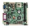
Chapter 1 Mainboard Layout Top: Mouse Bottom: Keyboard VGA-Out Top: RJ45 Bottom: USB Top: Parallel Bottom: COM1 Top: Line-In Middle: Line-Out Bottom: Microphone Back Panel PS2_MS ATXPWR CPU DIMM CPUFAN SYSFAN IDE1 FIR SMBUS COM2 CI F_AUDIO USB 3/4 CIR CMOS BATTERY CLEAR_CMOS BIOS Socket IDE2 CD_IN PCI1 RJ45 WOL FAN3 F_PANEL Parallel (LPT1) Line-In Line-Out Microphone PS2_KB VGA Out USB COM1 1-4
Chapter 1 Mainboard Layout Top: Mouse Bottom: Keyboard VGA-Out Top: RJ45 Bottom: USB Top: Parallel Bottom: COM1 Top: Line-In Middle: Line-Out Bottom: Microphone Back Panel PS2_MS ATXPWR CPU DIMM CPUFAN SYSFAN IDE1 FIR SMBUS COM2 CI F_AUDIO USB 3/4 CIR CMOS BATTERY CLEAR_CMOS BIOS Socket IDE2 CD_IN PCI1 RJ45 WOL FAN3 F_PANEL Parallel (LPT1) Line-In Line-Out Microphone PS2_KB VGA Out USB COM1 1-4

User Manual
Page 13
... chapter includes the following sections: CPU Memory Module Installation Connecting the Power Supply Back Panel Ports Connectors Jumpers Slots 2-2 2-4 2-6 2-7 2-12 2-19 2-20 2-1 While installing the mainboard, carefully hold the components and closely follow the installation procedures. It is recommended to use a grounded wrist strap before handling computer components. Chapter Installation This...
... chapter includes the following sections: CPU Memory Module Installation Connecting the Power Supply Back Panel Ports Connectors Jumpers Slots 2-2 2-4 2-6 2-7 2-12 2-19 2-20 2-1 While installing the mainboard, carefully hold the components and closely follow the installation procedures. It is recommended to use a grounded wrist strap before handling computer components. Chapter Installation This...
User Manual
Page 14
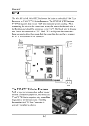
...2-2 The black wire is an additional FAN connector. SYSFAN CPUFAN Sensor +12V GND FAN3 The VIA C3TM E-Series Processor With low power consumption and advanced thermal dissipation properties, the embedded VIA C3TM E-Series requires only a small fan to detect fan speed, but the power fan does ... maintain system cooling. Both CPU and System fan connectors have sensors to guarantee performance and reliability. Chapter 2 CPU The VIA EPIA-ML Mini-ITX Mainboard includes an embedded VIA Eden Processor or VIA C3TM E-Series Processor. FAN3 is Ground and should be connected to the +12V.
...2-2 The black wire is an additional FAN connector. SYSFAN CPUFAN Sensor +12V GND FAN3 The VIA C3TM E-Series Processor With low power consumption and advanced thermal dissipation properties, the embedded VIA C3TM E-Series requires only a small fan to detect fan speed, but the power fan does ... maintain system cooling. Both CPU and System fan connectors have sensors to guarantee performance and reliability. Chapter 2 CPU The VIA EPIA-ML Mini-ITX Mainboard includes an embedded VIA Eden Processor or VIA C3TM E-Series Processor. FAN3 is Ground and should be connected to the +12V.

User Manual
Page 16
DDR SDRAM Module Installation Procedures 1. Align the DDR SDRAM module with the corresponding notches on the DIMM slot. Push the white retaining latches at either end of the DIMM slot outwards. 2. Chapter 2 Memory Module Installation The VIA EPIA-ML Mini-ITX Mainboard provides one 184-pin DIMM slot for DDR266 SDRAM memory modules. With both hands, press the DDR SDRAM module down into the DIMM slot so that the white retaining latches rotate up and secure the module in the correct position. 3. The modules will only fit if placed in place (see picture below). 2-4
DDR SDRAM Module Installation Procedures 1. Align the DDR SDRAM module with the corresponding notches on the DIMM slot. Push the white retaining latches at either end of the DIMM slot outwards. 2. Chapter 2 Memory Module Installation The VIA EPIA-ML Mini-ITX Mainboard provides one 184-pin DIMM slot for DDR266 SDRAM memory modules. With both hands, press the DDR SDRAM module down into the DIMM slot so that the white retaining latches rotate up and secure the module in the correct position. 3. The modules will only fit if placed in place (see picture below). 2-4

User Manual
Page 17
Installation Available DDR SDRAM Configurations Refer to the table below for available DDR SDRAM configurations on the mainboard. Slot Memory Module DIMM (Bank 0 & 1) 64MB, 128MB, 256MB, 512MB, 1GB Maximum System Memory Supported Total Memory 64 MB - 1 GB 64 MB - 1 GB 2-5
Installation Available DDR SDRAM Configurations Refer to the table below for available DDR SDRAM configurations on the mainboard. Slot Memory Module DIMM (Bank 0 & 1) 64MB, 128MB, 256MB, 512MB, 1GB Maximum System Memory Supported Total Memory 64 MB - 1 GB 64 MB - 1 GB 2-5

User Manual
Page 18
.... ATX 20-Pin Power Connector To connect the ATX power supply, make sure that no damage will be connected. Chapter 2 Connecting the Power Supply The VIA EPIA-ML Mini-ITX Mainboard requires an ATX power supply to ensure that all components are correctly aligned.
.... ATX 20-Pin Power Connector To connect the ATX power supply, make sure that no damage will be connected. Chapter 2 Connecting the Power Supply The VIA EPIA-ML Mini-ITX Mainboard requires an ATX power supply to ensure that all components are correctly aligned.

User Manual
Page 19
... back panel has the following ports: PS2_MS RJ45 Parallel (LPT1) Installation Line-In Line-Out Microphone PS2_KB VGA Out USB COM1 Mouse Port: PS2_MS The mainboard provides a standard PS/2 mouse connector for attaching a PS/2 keyboard. Pin Signal Description 6 5 1 4 3 2 2 1 3 4 PS2 Keyboard (6-pin female) 5 Keyboard DATA NC GND VCC Keyboard...6 Signal Mouse DATA NC GND VCC Mouse Clock NC Description Mouse data No connection Ground +5V Mouse clock No connection Keyboard Port: PS2_KB The mainboard provides a standard PS/2 keyboard connector for attaching a PS/2 mouse.
... back panel has the following ports: PS2_MS RJ45 Parallel (LPT1) Installation Line-In Line-Out Microphone PS2_KB VGA Out USB COM1 Mouse Port: PS2_MS The mainboard provides a standard PS/2 mouse connector for attaching a PS/2 keyboard. Pin Signal Description 6 5 1 4 3 2 2 1 3 4 PS2 Keyboard (6-pin female) 5 Keyboard DATA NC GND VCC Keyboard...6 Signal Mouse DATA NC GND VCC Mouse Clock NC Description Mouse data No connection Ground +5V Mouse clock No connection Keyboard Port: PS2_KB The mainboard provides a standard PS/2 keyboard connector for attaching a PS/2 mouse.

User Manual
Page 20
Chapter 2 VGA Out A DB-15 pin female connector that connects to the Local Area Network (LAN). Pin Signal Description 1 VCC + 5V 2 - DATA Negative data channel 3 + DATA Positive data channel 4 GND Ground 1 234 RJ45 10/100 NIC Port The mainboard provides one standard RJ-45 port for connection to a VGA monitor. USB Ports The mainboard provides 2 USB 2.0 ports. You can be plugged directly into these ports. USB-compatible devices can connect a network cable to the LAN port. 2-8
Chapter 2 VGA Out A DB-15 pin female connector that connects to the Local Area Network (LAN). Pin Signal Description 1 VCC + 5V 2 - DATA Negative data channel 3 + DATA Positive data channel 4 GND Ground 1 234 RJ45 10/100 NIC Port The mainboard provides one standard RJ-45 port for connection to a VGA monitor. USB Ports The mainboard provides 2 USB 2.0 ports. You can be plugged directly into these ports. USB-compatible devices can connect a network cable to the LAN port. 2-8

User Manual
Page 21
... 7 Acknowledge Busy Paper End Select Automatic Feed Error Initialize Printer Select In Ground Ground Ground Ground Ground Ground Ground Ground 2-9 Installation Parallel Port: LPT1 The mainboard provides a 25-pin female connector for LPT (parallel port).
... 7 Acknowledge Busy Paper End Select Automatic Feed Error Initialize Printer Select In Ground Ground Ground Ground Ground Ground Ground Ground 2-9 Installation Parallel Port: LPT1 The mainboard provides a 25-pin female connector for LPT (parallel port).

User Manual
Page 22
... headphones. The Line-In jack is for connecting to an external audio device such as a CD player, tape player, etc.... Chapter 2 Serial Ports: COM1 The mainboard offers two 9-pin male Serial Port connectors COM1.
... headphones. The Line-In jack is for connecting to an external audio device such as a CD player, tape player, etc.... Chapter 2 Serial Ports: COM1 The mainboard offers two 9-pin male Serial Port connectors COM1.

User Manual
Page 24
... (Secondary IDE Connector) IDE2 can connect up to IDE1. You can also connect a Master and a Slave drive. Chapter 2 Connectors Hard Disk Connectors: IDE1 & IDE2 The mainboard has a 32-bit Enhanced PCI IDE and Ultra DMA 33/66/100/ 133 controller that provides PIO mode 0~4, Bus Master, and Ultra DMA 33/ 66...
... (Secondary IDE Connector) IDE2 can connect up to IDE1. You can also connect a Master and a Slave drive. Chapter 2 Connectors Hard Disk Connectors: IDE1 & IDE2 The mainboard has a 32-bit Enhanced PCI IDE and Ultra DMA 33/66/100/ 133 controller that provides PIO mode 0~4, Bus Master, and Ultra DMA 33/ 66...

User Manual
Page 27
The connector will power up to connect a network card with the Wake-On LAN function. Installation USB pin-header: USB3/4 The mainboard provides 1 front USB pin-header connector, allowing up the system when a signal is received through the network card. Please note that the function of ACPI ...
The connector will power up to connect a network card with the Wake-On LAN function. Installation USB pin-header: USB3/4 The mainboard provides 1 front USB pin-header connector, allowing up the system when a signal is received through the network card. Please note that the function of ACPI ...

User Manual
Page 30
To connect the front audio cable, first remove the two red plastic jumpers. Pin Signal Pin Signal 1 FRN_MIC 2 AGND 3 AUD_MIC_BIAS 4 +5V 5 LINE_OUT_R 6 Next_R 7 NC 8 Keypin 9 LINE_OUT_L 10 Next_L F-AUDIO 1 2 9 10 2-18 Only the line-out and microphone functions are available for use on the front panel. Chapter 2 Front Audio Panel: F_AUDIO This connector allows you to connect a front audio panel to the mainboard.
To connect the front audio cable, first remove the two red plastic jumpers. Pin Signal Pin Signal 1 FRN_MIC 2 AGND 3 AUD_MIC_BIAS 4 +5V 5 LINE_OUT_R 6 Next_R 7 NC 8 Keypin 9 LINE_OUT_L 10 Next_L F-AUDIO 1 2 9 10 2-18 Only the line-out and microphone functions are available for use on the front panel. Chapter 2 Front Audio Panel: F_AUDIO This connector allows you to connect a front audio panel to the mainboard.

User Manual
Page 31
... 2-3 pin position. Then return it to clear the system configuration data from the CMOS RAM, use of at least 5 years. Jumpers Installation The mainboard provides jumpers for your mainboard's functions through the use the CLEAR_CMOS (Clear CMOS jumper). Clear CMOS: CLEAR_CMOS The onboard CMOS RAM stores system configuration data and has an... 123 CLEAR_CMOS 2-19 You can clear the CMOS by shorting 1-2 pin while the system is on will explain how to change settings for setting the mainboard's functions. Shorting the jumper while the system is off. This section will damage the...
... 2-3 pin position. Then return it to clear the system configuration data from the CMOS RAM, use of at least 5 years. Jumpers Installation The mainboard provides jumpers for your mainboard's functions through the use the CLEAR_CMOS (Clear CMOS jumper). Clear CMOS: CLEAR_CMOS The onboard CMOS RAM stores system configuration data and has an... 123 CLEAR_CMOS 2-19 You can clear the CMOS by shorting 1-2 pin while the system is on will explain how to change settings for setting the mainboard's functions. Shorting the jumper while the system is off. This section will damage the...
User Manual
Page 43
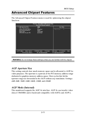
... BIOS Setup The Advanced Chipset Features menu is used for video purposes. Settings: 4MB, 8MB, 16MB, 32MB, 64MB, 128MB, and 256MB AGP Mode (Internal) This mainboard supports the AGP 4x interface.
... BIOS Setup The Advanced Chipset Features menu is used for video purposes. Settings: 4MB, 8MB, 16MB, 32MB, 64MB, 128MB, and 256MB AGP Mode (Internal) This mainboard supports the AGP 4x interface.

User Manual
Page 46
... disabled. Settings: Auto and Disabled VIA OnChip LAN This setting allows you... DOS and Windows. if not, it is disabled. If the device is detected, the onboard VIA MC'97 (Modem Codec'97) controller will be enabled; This field is only available if Onboard... available if Onboard Fast IR is enabled. If the device is detected, the onboard VIA AC'97 (Audio Codec'97) controller will be enabled; Settings: Enabled and Disabled ...Lan Boot ROM for DOS and Windows. Disable the controller if you to make VIA OnChip LAN enabled or disabled. Settings: Enabled and Disabled Fast IR IRQ Set ...
... disabled. Settings: Auto and Disabled VIA OnChip LAN This setting allows you... DOS and Windows. if not, it is disabled. If the device is detected, the onboard VIA MC'97 (Modem Codec'97) controller will be enabled; This field is only available if Onboard... available if Onboard Fast IR is enabled. If the device is detected, the onboard VIA AC'97 (Audio Codec'97) controller will be enabled; Settings: Enabled and Disabled ...Lan Boot ROM for DOS and Windows. Disable the controller if you to make VIA OnChip LAN enabled or disabled. Settings: Enabled and Disabled Fast IR IRQ Set ...