User Manual
Page 6
... Installation 2-2 Memory Module Installation 2-4 Connecting the Power Supply 2-6 Back Panel Ports 2-7 Connectors 2-12 Jumpers 2-19 Slots 2-20 Chapter 3: BIOS Setup 3-1 Entering Setup 3-2 Control Keys 3-2 Gettings Help 3-3 The Main Menu 3-4 Standard CMOS Features 3-6 Advanced BIOS Features 3-8 Advanced Chipset Features 3-11 Integrated Peripherals 3-13 Power Management Setup 3-17 PNP / PCI Configurations 3-22 PC Health...
... Installation 2-2 Memory Module Installation 2-4 Connecting the Power Supply 2-6 Back Panel Ports 2-7 Connectors 2-12 Jumpers 2-19 Slots 2-20 Chapter 3: BIOS Setup 3-1 Entering Setup 3-2 Control Keys 3-2 Gettings Help 3-3 The Main Menu 3-4 Standard CMOS Features 3-6 Advanced BIOS Features 3-8 Advanced Chipset Features 3-11 Integrated Peripherals 3-13 Power Management Setup 3-17 PNP / PCI Configurations 3-22 PC Health...
User Manual
Page 9
can be switched to 6 channel output with Smart 5.1 BIOS • AwardBIOS with 2 / 4Mbit flash memory Form Factor • 17 cm X 17 cm Mini-ITX (4 layers) 1-3 Specifications Onboard I/O Connectors • Front-panel audio connectors (Mic and Line Out) • CD Audio-in connector • 1 FIR connector; 1 PS2 connector • Wake-...
can be switched to 6 channel output with Smart 5.1 BIOS • AwardBIOS with 2 / 4Mbit flash memory Form Factor • 17 cm X 17 cm Mini-ITX (4 layers) 1-3 Specifications Onboard I/O Connectors • Front-panel audio connectors (Mic and Line Out) • CD Audio-in connector • 1 FIR connector; 1 PS2 connector • Wake-...

User Manual
Page 10
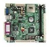
Chapter 1 Mainboard Layout Top: Mouse Bottom: Keyboard VGA-Out Top: RJ45 Bottom: USB Top: Parallel Bottom: COM1 Top: Line-In Middle: Line-Out Bottom: Microphone Back Panel PS2_MS ATXPWR CPU DIMM CPUFAN SYSFAN IDE1 FIR SMBUS COM2 CI F_AUDIO USB 3/4 CIR CMOS BATTERY CLEAR_CMOS BIOS Socket IDE2 CD_IN PCI1 RJ45 WOL FAN3 F_PANEL Parallel (LPT1) Line-In Line-Out Microphone PS2_KB VGA Out USB COM1 1-4
Chapter 1 Mainboard Layout Top: Mouse Bottom: Keyboard VGA-Out Top: RJ45 Bottom: USB Top: Parallel Bottom: COM1 Top: Line-In Middle: Line-Out Bottom: Microphone Back Panel PS2_MS ATXPWR CPU DIMM CPUFAN SYSFAN IDE1 FIR SMBUS COM2 CI F_AUDIO USB 3/4 CIR CMOS BATTERY CLEAR_CMOS BIOS Socket IDE2 CD_IN PCI1 RJ45 WOL FAN3 F_PANEL Parallel (LPT1) Line-In Line-Out Microphone PS2_KB VGA Out USB COM1 1-4

User Manual
Page 26
Pin Signal Pin Signal 1 +5V 2 GND 3 KB_CLK 4 KB_DATA 5 EXT_KBCLK 6 EXT_KBDATA 7 MS_CLK 8 MS_DATA 9 EXT_MSCLK 10 EXT_MSDATA 2-14 2 10 1 9 CIR / EXT_KBMS You must configure the setting through the BIOS setup to connect an IrDA Infrared module. Pin Signal 1 VCC 2 IRRX1 3 IRRX 4 GND 5 IRTX FIR 1 5 Consumer Infrared Module, PS2 Header: CIR / EXT_KBMS When the header is not in use, please short pin 3&5, pin 4&6, pin 7&9, and pin 8&10. Chapter 2 Fast IrDA Infrared Module Connector: IR This connector allows you to activate the IR function.
Pin Signal Pin Signal 1 +5V 2 GND 3 KB_CLK 4 KB_DATA 5 EXT_KBCLK 6 EXT_KBDATA 7 MS_CLK 8 MS_DATA 9 EXT_MSCLK 10 EXT_MSDATA 2-14 2 10 1 9 CIR / EXT_KBMS You must configure the setting through the BIOS setup to connect an IrDA Infrared module. Pin Signal 1 VCC 2 IRRX1 3 IRRX 4 GND 5 IRTX FIR 1 5 Consumer Infrared Module, PS2 Header: CIR / EXT_KBMS When the header is not in use, please short pin 3&5, pin 4&6, pin 7&9, and pin 8&10. Chapter 2 Fast IrDA Infrared Module Connector: IR This connector allows you to activate the IR function.

User Manual
Page 32
... hardware lines over which devices can send interrupt signals to make sure that you to the PCI bus INT A# ~ INT D# pins as jumpers, switches or BIOS configuration. Chapter 2 Slots Peripheral Component Interconnect: PCI The PCI slot allows you unplug the power supply first. When adding or removing expansion cards, make any...
... hardware lines over which devices can send interrupt signals to make sure that you to the PCI bus INT A# ~ INT D# pins as jumpers, switches or BIOS configuration. Chapter 2 Slots Peripheral Component Interconnect: PCI The PCI slot allows you unplug the power supply first. When adding or removing expansion cards, make any...
User Manual
Page 33
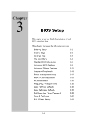
Chapter BIOS Setup This chapter gives you detailed explaination of each BIOS setup functions. This chapter includes the following sections: Entering Setup Control Keys Gettings Help The Main Menu Standard CMOS Features Advanced BIOS Features Advanced Chipset Features Integrated Peripherals Power Management Setup PNP / PCI Configurations PC Health Status Frequency / Voltage Control Load Fail-Safe Defaults Load Optimized Defaults Set Supervisor / User Password Save & Exit Setup Exit Without Saving 3-2 3-2 3-3 3-4 3-6 3-8 3-11 3-13 3-17 3-22 3-25 3-26 3-28 3-29 3-30 3-32 3-33 3-1
Chapter BIOS Setup This chapter gives you detailed explaination of each BIOS setup functions. This chapter includes the following sections: Entering Setup Control Keys Gettings Help The Main Menu Standard CMOS Features Advanced BIOS Features Advanced Chipset Features Integrated Peripherals Power Management Setup PNP / PCI Configurations PC Health Status Frequency / Voltage Control Load Fail-Safe Defaults Load Optimized Defaults Set Supervisor / User Password Save & Exit Setup Exit Without Saving 3-2 3-2 3-3 3-4 3-6 3-8 3-11 3-13 3-17 3-22 3-25 3-26 3-28 3-29 3-30 3-32 3-33 3-1

User Manual
Page 34
... the default CMOS value from Fail-Safe default table, only for Option Page Setup Menu Load Optimized defaults Jumps to enter the BIOS setup menu. If you missed the BIOS setup entry point, you may restart the system and try again. Chapter 3 Entering Setup Power on the computer and press Delete straight...
... the default CMOS value from Fail-Safe default table, only for Option Page Setup Menu Load Optimized defaults Jumps to enter the BIOS setup menu. If you missed the BIOS setup entry point, you may restart the system and try again. Chapter 3 Entering Setup Power on the computer and press Delete straight...

User Manual
Page 35
... from the sub-menu press Esc. The help screen. 3-3 General Help: F1 The BIOS setup program provides a General Help screen. Getting Help BIOS Setup Main Menu The main menu displays all BIOS setup categories. You can use and navigate the BIOS setup. Press Esc to exit the help screen displays the keys for use...
... from the sub-menu press Esc. The help screen. 3-3 General Help: F1 The BIOS setup program provides a General Help screen. Getting Help BIOS Setup Main Menu The main menu displays all BIOS setup categories. You can use and navigate the BIOS setup. Press Esc to exit the help screen displays the keys for use...

User Manual
Page 36
...PCI configurations. PC Health Status This menu shows the PC health status. 3-4 AwardBIOS CMOS Setup Utility Standard CMOS Features Advanced BIOS Features Advanced Chipset Features Integrated Peripherals Power Management Setup PnP / PCI Configurations PC Health Status Frequency / Voltage Control Load Fail... Date, Hard Disk Type... Advanced Chipset Features Use this menu to set the advanced features available on your system. Advanced BIOS Features Use this menu to set chipset specific features and optimize system performance. Standard CMOS Features Use this menu to set basic...
...PCI configurations. PC Health Status This menu shows the PC health status. 3-4 AwardBIOS CMOS Setup Utility Standard CMOS Features Advanced BIOS Features Advanced Chipset Features Integrated Peripherals Power Management Setup PnP / PCI Configurations PC Health Status Frequency / Voltage Control Load Fail... Date, Hard Disk Type... Advanced Chipset Features Use this menu to set the advanced features available on your system. Advanced BIOS Features Use this menu to set chipset specific features and optimize system performance. Standard CMOS Features Use this menu to set basic...

User Manual
Page 37
... and voltage control. Exit Without Saving Abandon all BIOS setting changes and exit setup. 3-5 Load Optimized Defaults Use this menu option to set the BIOS user password. Set User Password Use this menu option to load the BIOS default settings for optimal and high performance system operations.... Save & Exit Setup Save BIOS setting changes and exit setup. Load Fail-Safe Defaults ...
... and voltage control. Exit Without Saving Abandon all BIOS setting changes and exit setup. 3-5 Load Optimized Defaults Use this menu option to set the BIOS user password. Set User Password Use this menu option to load the BIOS default settings for optimal and high performance system operations.... Save & Exit Setup Save BIOS setting changes and exit setup. Load Fail-Safe Defaults ...
User Manual
Page 39
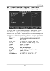
... the menu. The settings are CHS, LBA, Large, Auto. Number of the storage device. The settings are None, Auto, Manual. The formatted size of sectors. BIOS Setup IDE Primary Master/Slave, Secondary Master/Slave Press Enter to enter the sub-menu and the following screen appears: IDE HDD Auto-Detection Phoenix...
... the menu. The settings are CHS, LBA, Large, Auto. Number of the storage device. The settings are None, Auto, Manual. The formatted size of sectors. BIOS Setup IDE Primary Master/Slave, Secondary Master/Slave Press Enter to enter the sub-menu and the following screen appears: IDE HDD Auto-Detection Phoenix...

User Manual
Page 40
...for IDE Hard Disk Boot sector protection. Settings: Enabled and Disabled 3-8 If this function is enabled, any attempt to write data into this area, BIOS will cause a beep and warning message display on screen and alarm beep. : Move Enter: Select F5: Previous Values +/-/PU/PD: Value F10:... IDE Hard Disk boot sector protection. Facilitates error detection/correction when data passes through Level 2 cache. AwardBIOS CMOS Setup Utility Advanced BIOS Features Virus Warning CPU L2 Cache ECC Checking Quick Power On Self Test First Boot Device Second Boot Device Third Boot Device Boot ...
...for IDE Hard Disk Boot sector protection. Settings: Enabled and Disabled 3-8 If this function is enabled, any attempt to write data into this area, BIOS will cause a beep and warning message display on screen and alarm beep. : Move Enter: Select F5: Previous Values +/-/PU/PD: Value F10:... IDE Hard Disk boot sector protection. Facilitates error detection/correction when data passes through Level 2 cache. AwardBIOS CMOS Setup Utility Advanced BIOS Features Virus Warning CPU L2 Cache ECC Checking Quick Power On Self Test First Boot Device Second Boot Device Third Boot Device Boot ...

User Manual
Page 41
... HDD. Settings: On and Off Typematic Rate Setting When Enabled, you can set the Typematic Rate and Typematic Delay. BIOS Setup First/Second/Third Boot Device Set the boot device sequence as BIOS attempts to boot from the First/Second/Third boot device. The system will boot from ATAPI ZIP drive. The...
... HDD. Settings: On and Off Typematic Rate Setting When Enabled, you can set the Typematic Rate and Typematic Delay. BIOS Setup First/Second/Third Boot Device Set the boot device sequence as BIOS attempts to boot from the First/Second/Third boot device. The system will boot from ATAPI ZIP drive. The...

User Manual
Page 42
... Setup The password prompt appears only when end users try to run Setup. Settings: Enabled and Disabled Show Summary Information Show the summary information during BIOS bootup process. Settings: 6, 8, 10, 12, 15, 20, 24 and 30 Typematic Delay (Msec) When Typematic Rate Setting is enabled, this... select the delay between when the key was first pressed and when the acceleration begins. Display Full Screen Logo Show full screen logo during BIOS bootup process. Chapter 3 Typematic Rate (Chars/Sec) When Typematic Rate Setting is enabled, this item allows you to set a password,...
... Setup The password prompt appears only when end users try to run Setup. Settings: Enabled and Disabled Show Summary Information Show the summary information during BIOS bootup process. Settings: 6, 8, 10, 12, 15, 20, 24 and 30 Typematic Delay (Msec) When Typematic Rate Setting is enabled, this... select the delay between when the key was first pressed and when the acceleration begins. Display Full Screen Logo Show full screen logo during BIOS bootup process. Chapter 3 Typematic Rate (Chars/Sec) When Typematic Rate Setting is enabled, this item allows you to set a password,...
User Manual
Page 43
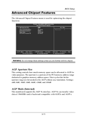
... backward-compatible with the chipset. The aperture is a portion of the PCI memory address range dedicated to the AGP without any translation. Advanced Chipset Features BIOS Setup The Advanced Chipset Features menu is used for video purposes.
... backward-compatible with the chipset. The aperture is a portion of the PCI memory address range dedicated to the AGP without any translation. Advanced Chipset Features BIOS Setup The Advanced Chipset Features menu is used for video purposes.
User Manual
Page 45
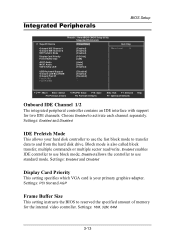
...also called block transfer, multiple commands or multiple sector read/write. Settings: PCI Slot and AGP Frame Buffer Size This setting instructs the BIOS to use standard mode. AwardBIOS CMOS Setup Utility Integrated Peripherals [Press Enter] Item Help Onboard IDE Channel 1 Onboard IDE Channel 2 ...IDE Prefetch Mode Display Card Priority Frame Buffer Size AC97 Audio MC97 Audio VIA OnChip LAN [Enabled] [Enabled] [Enabled] [PCI Slot] [32M] [Auto] [Auto] [Enabled] Menu Level USB Keyboard Support Onboard LAN Boot...
...also called block transfer, multiple commands or multiple sector read/write. Settings: PCI Slot and AGP Frame Buffer Size This setting instructs the BIOS to use standard mode. AwardBIOS CMOS Setup Utility Integrated Peripherals [Press Enter] Item Help Onboard IDE Channel 1 Onboard IDE Channel 2 ...IDE Prefetch Mode Display Card Priority Frame Buffer Size AC97 Audio MC97 Audio VIA OnChip LAN [Enabled] [Enabled] [Enabled] [PCI Slot] [32M] [Auto] [Auto] [Enabled] Menu Level USB Keyboard Support Onboard LAN Boot...
User Manual
Page 47
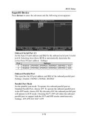
... port mode. To operate the onboard parallel port as Standard Parallel Port, choose SPP. Selecting Auto allows BIOS to support both the ECP and EPP modes simultaneously. Settings: SPP, EPP, ECP, ECP + EPP 3-15 BIOS Setup SuperIO Device Press Enter to enter the sub-menu and the following screen appears: Onboard Serial...
... port mode. To operate the onboard parallel port as Standard Parallel Port, choose SPP. Selecting Auto allows BIOS to support both the ECP and EPP modes simultaneously. Settings: SPP, EPP, ECP, ECP + EPP 3-15 BIOS Setup SuperIO Device Press Enter to enter the sub-menu and the following screen appears: Onboard Serial...

User Manual
Page 49
... Configuration and Power Management) Function. If your own style of computer use. S1(POS): System in power saving mode. Power Management Setup BIOS Setup The Power Management Setup menu configures the system to most effectively save energy while operating in a manner consistent with your operating system is...a "wakeup" event occurs. In this state, power is lost and hardware maintains all system context. The system context is saved to select how the BIOS put the system in low power mode S3(STR): All components are : S1(POS) S3(STR) S1 & S3 S1/Power On Suspend (POS)...
... Configuration and Power Management) Function. If your own style of computer use. S1(POS): System in power saving mode. Power Management Setup BIOS Setup The Power Management Setup menu configures the system to most effectively save energy while operating in a manner consistent with your operating system is...a "wakeup" event occurs. In this state, power is lost and hardware maintains all system context. The system context is saved to select how the BIOS put the system in low power mode S3(STR): All components are : S1(POS) S3(STR) S1 & S3 S1/Power On Suspend (POS)...

User Manual
Page 50
... Off Option Select whether or not to turn off when system enters power saving mode. Chapter 3 HDD Power Down Set the time to run VGA BIOS if resumed from S3 state. Settings: Auto, Yes and No 3-18 Settings are : Delay 4 Sec Instant-Off The system is turned off the screen when...
... Off Option Select whether or not to turn off when system enters power saving mode. Chapter 3 HDD Power Down Set the time to run VGA BIOS if resumed from S3 state. Settings: Auto, Yes and No 3-18 Settings are : Delay 4 Sec Instant-Off The system is turned off the screen when...

User Manual
Page 51
BIOS Setup Peripheral Activities Press Enter to change Password, 8 characters maximum. Settings: Off and On LPT & COM Event Decide whether or not the power management unit ...
BIOS Setup Peripheral Activities Press Enter to change Password, 8 characters maximum. Settings: Off and On LPT & COM Event Decide whether or not the power management unit ...