User Manual
Page 1
User's Manual EPIA-M Mini-ITX Mainboard P/N: 99-51-012561-14 Version 1.52 January 30, 2012
User's Manual EPIA-M Mini-ITX Mainboard P/N: 99-51-012561-14 Version 1.52 January 30, 2012

User Manual
Page 2
... specifications within this document. Disclaimer No license is a registered trademark of IBM Corporation. Copyright Copyright by VIA Technologies Inc. ("VIA"). Trademarks All trademarks are registered trademarks of this manual may arise from VIA. No part of Microsoft. However, VIA Technologies assumes no warranties, implied or otherwise, in regard to this document and to the products...
... specifications within this document. Disclaimer No license is a registered trademark of IBM Corporation. Copyright Copyright by VIA Technologies Inc. ("VIA"). Trademarks All trademarks are registered trademarks of this manual may arise from VIA. No part of Microsoft. However, VIA Technologies assumes no warranties, implied or otherwise, in regard to this document and to the products...

User Manual
Page 3
... personal expense. This equipment generates, uses and can radiate radio frequency energy and, if not installed and used in order to comply with the instruction manual, may cause harmful interference to radio communications. These limits are designed to provide reasonable protection against harmful interference when the equipment is likely to cause...
... personal expense. This equipment generates, uses and can radiate radio frequency energy and, if not installed and used in order to comply with the instruction manual, may cause harmful interference to radio communications. These limits are designed to provide reasonable protection against harmful interference when the equipment is likely to cause...

User Manual
Page 4
...surface before setting it up. 5. Never pour any add-on card or module. 9. Make sure the voltage of breakage 12. Keep this User's Manual for this equipment on the equipment should be noted. 10. Do not reuse, recharge, or reheat an old battery. Do not attempt to the power...The power cord or plug is damaged • Liquid has penetrated into the opening. Safety Instructions 1. The openings on it work according to User's Manual. • The equipment has dropped and damaged • If the equipment has obvious sign of the power source and adjust properly 110/220V before ...
...surface before setting it up. 5. Never pour any add-on card or module. 9. Make sure the voltage of breakage 12. Keep this User's Manual for this equipment on the equipment should be noted. 10. Do not reuse, recharge, or reheat an old battery. Do not attempt to the power...The power cord or plug is damaged • Liquid has penetrated into the opening. Safety Instructions 1. The openings on it work according to User's Manual. • The equipment has dropped and damaged • If the equipment has obvious sign of the power source and adjust properly 110/220V before ...

User Manual
Page 28
... pin-header. Please note that the function of ACPI WOL may be disabled when users unplug the power cord or turn off the power button manually. 20 Chapter 2 USB pin-header: USB3/4 The mainboard provides 1 front USB pin-header connector, allowing up the system when a signal is received through the network...
... pin-header. Please note that the function of ACPI WOL may be disabled when users unplug the power cord or turn off the power button manually. 20 Chapter 2 USB pin-header: USB3/4 The mainboard provides 1 front USB pin-header connector, allowing up the system when a signal is received through the network...

User Manual
Page 41
If you enter incorrect information in this menu item will not work properly if you select Manual, make sure the information is from your drive must match with the drive table. The settings are Mode 0/1/2/3/4, Auto. Number of cylinders Number of heads ...Write precompensation Cylinder location of the landing zone Number of sectors The settings are None, Auto, Manual. BIOS Setup IDE Primary Master/Slave, Secondary Master/Slave Press Enter to enter the sub-menu and the following screen appears: The specifications of your...
If you enter incorrect information in this menu item will not work properly if you select Manual, make sure the information is from your drive must match with the drive table. The settings are Mode 0/1/2/3/4, Auto. Number of cylinders Number of heads ...Write precompensation Cylinder location of the landing zone Number of sectors The settings are None, Auto, Manual. BIOS Setup IDE Primary Master/Slave, Secondary Master/Slave Press Enter to enter the sub-menu and the following screen appears: The specifications of your...

User Manual
Page 56
... Windows 95 or 98/98SE. When set to No, BIOS will initialize all the boot and Plug and Play compatible devices. Settings: Auto (ESCD) and Manual Assign IRQ For VGA/USB Assign IRQ for booting (VGA, IDE, SCSI). This section covers some very technical items and it is Plug & Play capable...
... Windows 95 or 98/98SE. When set to No, BIOS will initialize all the boot and Plug and Play compatible devices. Settings: Auto (ESCD) and Manual Assign IRQ For VGA/USB Assign IRQ for booting (VGA, IDE, SCSI). This section covers some very technical items and it is Plug & Play capable...
User Manual
Page 57
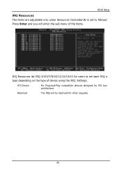
Settings: PCI Device For Plug-and-Play compatible devices designed for PCI bus architecture Reserved The IRQ will enter the sub-menu of the items. IRQ Resources list IRQ 3/4/5/7/9/10/11/12/14/15 for other requests 49 Press Enter and you will be reserved for users to set to Manual. BIOS Setup IRQ Resources The items are adjustable only when Resources Controlled By is set each IRQ a type depending on the type of device using the IRQ.
Settings: PCI Device For Plug-and-Play compatible devices designed for PCI bus architecture Reserved The IRQ will enter the sub-menu of the items. IRQ Resources list IRQ 3/4/5/7/9/10/11/12/14/15 for other requests 49 Press Enter and you will be reserved for users to set to Manual. BIOS Setup IRQ Resources The items are adjustable only when Resources Controlled By is set each IRQ a type depending on the type of device using the IRQ.

User Manual
Page 59
... BIOS Setup DRAM Clock The chipset supports synchronous and asynchronous mode between host clock and DRAM clock frequency. Settings: Manual and By SPD DRAM CAS Latency This item adjusts the speed it to "Manual". Generally, a lower setting will improve the performance of your system becomes less stable, you install new memory that...
... BIOS Setup DRAM Clock The chipset supports synchronous and asynchronous mode between host clock and DRAM clock frequency. Settings: Manual and By SPD DRAM CAS Latency This item adjusts the speed it to "Manual". Generally, a lower setting will improve the performance of your system becomes less stable, you install new memory that...

User Manual
Page 60
... time for the memory module. Settings: 2T Command, 1T Command DRAM Burst Len This field sets the length of time it takes to "Manual". Longer settings equal better memory performance. Lower setting equals faster command rate. Chapter 3 Bank Interleave Set the interleave mode of each bank. ...6V, 2.5V 52 This improves performance of the SDRAM by masking the refresh time of the SDRAM interface. Settings: 2T, 3T Active to "Manual". Longer values are safer but may not offer the best performance. Settings: 2T, 3T DRAM Command Rate This field controls how fast the memory...
... time for the memory module. Settings: 2T Command, 1T Command DRAM Burst Len This field sets the length of time it takes to "Manual". Longer settings equal better memory performance. Lower setting equals faster command rate. Chapter 3 Bank Interleave Set the interleave mode of each bank. ...6V, 2.5V 52 This improves performance of the SDRAM by masking the refresh time of the SDRAM interface. Settings: 2T, 3T Active to "Manual". Longer values are safer but may not offer the best performance. Settings: 2T, 3T DRAM Command Rate This field controls how fast the memory...

User Manual
Page 70
Please check that you can run the CD manually by typing "D:\Setup.exe" at Start\Run. Running the Driver Utilities CD To start using the CD, just simply insert the CD into your CD-...
Please check that you can run the CD manually by typing "D:\Setup.exe" at Start\Run. Running the Driver Utilities CD To start using the CD, just simply insert the CD into your CD-...