
User Manual
Page 6
TABLE OF CONTENTS Box Contents i Table of Contents ii Chapter 1 1 Specifications 1 Mainboard Specifications 2 Mainboard Layout 4 Back Panel Ports 5 Slots 5 Onboard Connectors and Jumpers 6 Chapter 2 7 Installation 7 CPU 8 Memory Module Installation 10 Connecting the Power Supply 12 Back Panel Ports 13 Connectors 17 Jumpers 25 Slots 26 Chapter 3 27 BIOS Setup 27 Entering ...
TABLE OF CONTENTS Box Contents i Table of Contents ii Chapter 1 1 Specifications 1 Mainboard Specifications 2 Mainboard Layout 4 Back Panel Ports 5 Slots 5 Onboard Connectors and Jumpers 6 Chapter 2 7 Installation 7 CPU 8 Memory Module Installation 10 Connecting the Power Supply 12 Back Panel Ports 13 Connectors 17 Jumpers 25 Slots 26 Chapter 3 27 BIOS Setup 27 Entering ...

User Manual
Page 10
...PCI slot • 1 x UltraDMA 66/100/133 Connector LAN • VIA VT6103 10/100 Base-T Ethernet PHY USB • USB v2.0 / v1.1 Firewire • IEEE 1394; Chapter 1 MAINBOARD SPECIFICATIONS CPU • • • VIA C3 / EDEN EBGA Processor (on board) Enhanced Ball Grid Array Package (...EBGA) Internal L1 128KB and L2 64KB cache memory Chipset • VIA CLE266 North Bridge • VT8235 South Bridge Graphics &#...
...PCI slot • 1 x UltraDMA 66/100/133 Connector LAN • VIA VT6103 10/100 Base-T Ethernet PHY USB • USB v2.0 / v1.1 Firewire • IEEE 1394; Chapter 1 MAINBOARD SPECIFICATIONS CPU • • • VIA C3 / EDEN EBGA Processor (on board) Enhanced Ball Grid Array Package (...EBGA) Internal L1 128KB and L2 64KB cache memory Chipset • VIA CLE266 North Bridge • VT8235 South Bridge Graphics &#...

User Manual
Page 11
... ports • Front-panel audio connectors (Mic and Line Out) • CD Audio-in connector • 1 FIR connector; 1 PS2 connector • Wake-on-LAN • CPU / System Fan / FAN3 • 1 I²C connector • 1 Connector for LVDS module (Optional) • Serial port connector for second COM port Back Panel I/O Ports • 1 PS2...; can be switched to 6 channel output with Smart 5.1 (See Appendix A) BIOS • Award BIOS with 2/4Mbit flash memory Form Factor • 17 cm X 17 cm Mini-ITX (4 layer) 3
... ports • Front-panel audio connectors (Mic and Line Out) • CD Audio-in connector • 1 FIR connector; 1 PS2 connector • Wake-on-LAN • CPU / System Fan / FAN3 • 1 I²C connector • 1 Connector for LVDS module (Optional) • Serial port connector for second COM port Back Panel I/O Ports • 1 PS2...; can be switched to 6 channel output with Smart 5.1 (See Appendix A) BIOS • Award BIOS with 2/4Mbit flash memory Form Factor • 17 cm X 17 cm Mini-ITX (4 layer) 3

User Manual
Page 14
... audio cable connector Consumer IR connector Jumper to reset CMOS settings to default Second serial port connector Connectors for optional front audio panel Case connectors CPU, System, Fan3 Floppy disk drive connector Fast Infrared Radiation connector I²C connector IDE hard disk drive connectors LVDS connector Sony Philips Digital Interface jumper Universal...
... audio cable connector Consumer IR connector Jumper to reset CMOS settings to default Second serial port connector Connectors for optional front audio panel Case connectors CPU, System, Fan3 Floppy disk drive connector Fast Infrared Radiation connector I²C connector IDE hard disk drive connectors LVDS connector Sony Philips Digital Interface jumper Universal...
User Manual
Page 16
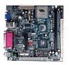
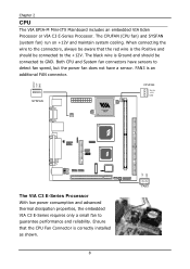
... fan to detect fan speed, but the power fan does not have a sensor. Ensure that the red wire is an additional FAN connector. The CPUFAN (CPU fan) and SYSFAN (system fan) run on +12V and maintain system cooling. Chapter 2 CPU The VIA EPIA-M Mini-ITX Mainboard includes an embedded VIA Eden Processor or VIA C3 E-Series Processor.
... fan to detect fan speed, but the power fan does not have a sensor. Ensure that the red wire is an additional FAN connector. The CPUFAN (CPU fan) and SYSFAN (system fan) run on +12V and maintain system cooling. Chapter 2 CPU The VIA EPIA-M Mini-ITX Mainboard includes an embedded VIA Eden Processor or VIA C3 E-Series Processor.

User Manual
Page 42
... feature for Level 2 cache. Allow BIOS to write data into this area will cause a beep and warning message display on screen. Settings: Disabled and Enabled CPU L2 Cache ECC Checking Set the ECC (Error-Correcting Code) feature for IDE Hard Disk boot sector protection. Settings: Enabled and Disabled 34 Facilitates error...
... feature for Level 2 cache. Allow BIOS to write data into this area will cause a beep and warning message display on screen. Settings: Disabled and Enabled CPU L2 Cache ECC Checking Set the ECC (Error-Correcting Code) feature for IDE Hard Disk boot sector protection. Settings: Enabled and Disabled 34 Facilitates error...

User Manual
Page 45
... wait after each write cycle until PCI bus signals that hit the aperture range are familiar with AGP2x and AGP1x. CPU to PCI POST Write When Enabled, CPU can write up to four words of the PCI memory address range dedicated to the AGP without any translation. Settings: Enabled and Disabled... 37 AGP Aperture Size This setting controls how much memory space can transfer video data at 1066MB/s and is used for video purposes. If Disabled, CPU must wait for PCI bus cycle to AGP for optimizing the chipset functions. Settings: 4MB, 8MB, 16MB, 32MB, 64MB, 128MB and 256MB AGP Mode (...
... wait after each write cycle until PCI bus signals that hit the aperture range are familiar with AGP2x and AGP1x. CPU to PCI POST Write When Enabled, CPU can write up to four words of the PCI memory address range dedicated to the AGP without any translation. Settings: Enabled and Disabled... 37 AGP Aperture Size This setting controls how much memory space can transfer video data at 1066MB/s and is used for video purposes. If Disabled, CPU must wait for PCI bus cycle to AGP for optimizing the chipset functions. Settings: 4MB, 8MB, 16MB, 32MB, 64MB, 128MB and 256MB AGP Mode (...

User Manual
Page 46
Settings: NTSC and PAL CPU Direct Access FB Enable the CPU to the native resolution of the display being used with the system. Chapter 3 Select Display Device This setting refers to the type of display being used with the system. Settings: Enabled and Disabled 38 Settings: 1600x1200, 1400.1050, 1280, 1024, 1280x768, 1024x768, 800x600 and 640x480 TV Type This setting refers to the native resolution of the display being used with the system. Settings: CRT, TV, CRT+TV, LCD and CRT+LCD Panel Type This setting refers to directly access the frame buffer.
Settings: NTSC and PAL CPU Direct Access FB Enable the CPU to the native resolution of the display being used with the system. Chapter 3 Select Display Device This setting refers to the type of display being used with the system. Settings: Enabled and Disabled 38 Settings: 1600x1200, 1400.1050, 1280, 1024, 1280x768, 1024x768, 800x600 and 640x480 TV Type This setting refers to the native resolution of the display being used with the system. Settings: CRT, TV, CRT+TV, LCD and CRT+LCD Panel Type This setting refers to directly access the frame buffer.

User Manual
Page 51
... 98/98SE/ME/2000/XP) select Enabled. In this state, power is lost and hardware maintains all system context. In this state, no system context (CPU or chipset) is supplied only to essential components such as main memory and wakeup-capable devices. ACPI Function Activate the ACPI (Advanced Configuration and Power...
... 98/98SE/ME/2000/XP) select Enabled. In this state, power is lost and hardware maintains all system context. In this state, no system context (CPU or chipset) is supplied only to essential components such as main memory and wakeup-capable devices. ACPI Function Activate the ACPI (Advanced Configuration and Power...

User Manual
Page 58
The PC Health Status displays the current status of all of your CPU, fan, warning for overall system status. Chapter 3 PC HEALTH STATUS This section shows the status of the monitored hardware devices/components such as CPU voltages, temperatures and fan speeds. 50
The PC Health Status displays the current status of all of your CPU, fan, warning for overall system status. Chapter 3 PC HEALTH STATUS This section shows the status of the monitored hardware devices/components such as CPU voltages, temperatures and fan speeds. 50