
User Manual
Page 2
..., chemical, manual or otherwise without the prior written permission of Phoenix Technologies Ltd. PS/2 is a registered trademark of VIA Technologies, Incorporated. Award BIOS is a registered trademark of their respective holders. Notice 2 Shielded interface cables and A.C. Trademarks All trademarks are designed to... this equipment in a residential area is operated in accordance with the emission limits. Copyright Copyright © 2010-2012 VIA Technologies Incorporated. This equipment generates, uses and can radiate radio frequency energy and, if not installed and used in ...
..., chemical, manual or otherwise without the prior written permission of Phoenix Technologies Ltd. PS/2 is a registered trademark of VIA Technologies, Incorporated. Award BIOS is a registered trademark of their respective holders. Notice 2 Shielded interface cables and A.C. Trademarks All trademarks are designed to... this equipment in a residential area is operated in accordance with the emission limits. Copyright Copyright © 2010-2012 VIA Technologies Incorporated. This equipment generates, uses and can radiate radio frequency energy and, if not installed and used in ...

User Manual
Page 6
... 2 9 Installation 9 CPU 10 Memory Module Installation 12 Connecting the Power Supply 13 Back Panel Ports 14 Connectors 17 Jumpers 25 Slots 27 Chapter 3 29 BIOS Setup 29 Entering Setup 30 Control Keys 31 Navigating the BIOS Menus 32 Getting Help 33 Main Menu 34 Standard CMOS Features 36 IDE Drives 37 Advanced...
... 2 9 Installation 9 CPU 10 Memory Module Installation 12 Connecting the Power Supply 13 Back Panel Ports 14 Connectors 17 Jumpers 25 Slots 27 Chapter 3 29 BIOS Setup 29 Entering Setup 30 Control Keys 31 Navigating the BIOS Menus 32 Getting Help 33 Main Menu 34 Standard CMOS Features 36 IDE Drives 37 Advanced...

User Manual
Page 12
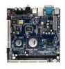
Chapter 1 BIOS • • Award BIOS with 4/8Mbit flash memory capacity ACPI2.0, SMBIOS2.1 and DMI2.2 Form Factor • Mini-ITX (6 layers) • 17 cm X 17 cm Note: Due to the hardware limitation, DDR2 SDRAM chips organized as 128Mb x 8 bank cannot be supported by EPIA products with CN700 and CX700M chipsets. 4
Chapter 1 BIOS • • Award BIOS with 4/8Mbit flash memory capacity ACPI2.0, SMBIOS2.1 and DMI2.2 Form Factor • Mini-ITX (6 layers) • 17 cm X 17 cm Note: Due to the hardware limitation, DDR2 SDRAM chips organized as 128Mb x 8 bank cannot be supported by EPIA products with CN700 and CX700M chipsets. 4

User Manual
Page 16
... System fan connector Universal Serial Bus 2.0 connectors 3-4 TV output connector ONBOARD JUMPERS Jumper CLEAR_CMOS PANEL SPDIF_SEL WP Description Reset CMOS settings IDE selector S/PDIF selector BIOS write protection setting Page 19 12 20 10 19 20 17 16 22 23 21-22 18 18 18 10 19 22 Page 24 25...
... System fan connector Universal Serial Bus 2.0 connectors 3-4 TV output connector ONBOARD JUMPERS Jumper CLEAR_CMOS PANEL SPDIF_SEL WP Description Reset CMOS settings IDE selector S/PDIF selector BIOS write protection setting Page 19 12 20 10 19 20 17 16 22 23 21-22 18 18 18 10 19 22 Page 24 25...

User Manual
Page 28
... that provides you fast data transfer rates. The mainboard has one FireWire pin header to provide PC connectivity for a wide range of 480 Mbps. The BIOS settings must be used to connect to an IrDA module. Chapter 2 USB Pin Connector: USB 5-6 The mainboard provides 1 front USB pin header, allowing up to...
... that provides you fast data transfer rates. The mainboard has one FireWire pin header to provide PC connectivity for a wide range of 480 Mbps. The BIOS settings must be used to connect to an IrDA module. Chapter 2 USB Pin Connector: USB 5-6 The mainboard provides 1 front USB pin header, allowing up to...

User Manual
Page 34
Chapter 2 BIOS Write Protection: WP This jumper allows you to protect from flashing the BIOS. BIOS WP Write Protection setting: pin1 = /WP & /TBL, pin2 = GND, short 1-2 1 (default) 26
Chapter 2 BIOS Write Protection: WP This jumper allows you to protect from flashing the BIOS. BIOS WP Write Protection setting: pin1 = /WP & /TBL, pin2 = GND, short 1-2 1 (default) 26

User Manual
Page 37
CHAPTER 3 BIOS Setup This chapter gives a detailed explanation of the BIOS setup functions. 29
CHAPTER 3 BIOS Setup This chapter gives a detailed explanation of the BIOS setup functions. 29

User Manual
Page 38
If you missed the BIOS setup entry point, you may restart the system and try again. 30 Chapter 3 ENTERING SETUP Power on the computer and press during the beginning of the boot sequence to enter the BIOS setup menu.
If you missed the BIOS setup entry point, you may restart the system and try again. 30 Chapter 3 ENTERING SETUP Power on the computer and press during the beginning of the boot sequence to enter the BIOS setup menu.

User Manual
Page 39
CONTROL KEYS Keys Up Arrow Down Arrow Left Arrow Right Arrow Enter Escape Page Up / + Page Down / F1 F5 F6 F7 F9 F10 BIOS Setup Description Move to the previous item Move to the next item Move to the item in the left side Move to the item in ...
CONTROL KEYS Keys Up Arrow Down Arrow Left Arrow Right Arrow Enter Escape Page Up / + Page Down / F1 F5 F6 F7 F9 F10 BIOS Setup Description Move to the previous item Move to the next item Move to the item in the left side Move to the item in ...

User Manual
Page 40
Use the control keys Up/Down arrow keys to a field indicates that a sub-menu is displayed at the bottom of the selected/highlighted category is available (see figure below). An arrow symbol next to select any item/sub-menu. Chapter 3 NAVIGATING THE BIOS MENUS The main menu displays all the BIOS setup categories. Description of the screen. Press to display the sub-menu. To exit the submenu, press . 32
Use the control keys Up/Down arrow keys to a field indicates that a sub-menu is displayed at the bottom of the selected/highlighted category is available (see figure below). An arrow symbol next to select any item/sub-menu. Chapter 3 NAVIGATING THE BIOS MENUS The main menu displays all the BIOS setup categories. Description of the screen. Press to display the sub-menu. To exit the submenu, press . 32

User Manual
Page 41
BIOS Setup GETTING HELP The BIOS setup program provides a "General Help" screen. The help screen. 33 You can display this screen from any menu/sub-menu by pressing . Press to exit the help screen displays the keys for using and navigating the BIOS setup.
BIOS Setup GETTING HELP The BIOS setup program provides a "General Help" screen. The help screen. 33 You can display this screen from any menu/sub-menu by pressing . Press to exit the help screen displays the keys for using and navigating the BIOS setup.

User Manual
Page 42
... Use this menu to set the PnP and PCI configurations. AwardBIOS CMOS Setup Utility Standard CMOS Features Advanced BIOS Features Advanced Chipset Features Integrated Peripherals Power Management Setup PnP / PCI Configurations PC Health Status Frequency / Voltage Control Load Fail-Safe ...Defaults Load Optimized Defaults Set Supervisor Password Set User Password Save & Exit Setup Exit Without Saving ESC : Quit F9 : Menu in BIOS F10 : Save & Exit Setup : Select Item Time, Date, Hard Disk Type... PnP/PCI Configurations Use this menu to set the advanced features available...
... Use this menu to set the PnP and PCI configurations. AwardBIOS CMOS Setup Utility Standard CMOS Features Advanced BIOS Features Advanced Chipset Features Integrated Peripherals Power Management Setup PnP / PCI Configurations PC Health Status Frequency / Voltage Control Load Fail-Safe ...Defaults Load Optimized Defaults Set Supervisor Password Set User Password Save & Exit Setup Exit Without Saving ESC : Quit F9 : Menu in BIOS F10 : Save & Exit Setup : Select Item Time, Date, Hard Disk Type... PnP/PCI Configurations Use this menu to set the advanced features available...

User Manual
Page 43
Set User Password Use this menu option to set the BIOS supervisor password. Load Optimized Defaults Use this menu option to load BIOS default settings for minimal and stable system operations. Exit Without Saving Discard all BIOS setting changes and exit setup. 35 Save & Exit Setup Save BIOS setting changes and exit setup. Set Supervisor Password Use this menu option to set the BIOS user password. BIOS Setup Load Fail-Safe Defaults Use this menu option to load the BIOS default settings for optimal and high performance system operations.
Set User Password Use this menu option to set the BIOS supervisor password. Load Optimized Defaults Use this menu option to load BIOS default settings for minimal and stable system operations. Exit Without Saving Discard all BIOS setting changes and exit setup. 35 Save & Exit Setup Save BIOS setting changes and exit setup. Set Supervisor Password Use this menu option to set the BIOS user password. BIOS Setup Load Fail-Safe Defaults Use this menu option to load the BIOS default settings for optimal and high performance system operations.

User Manual
Page 45
... the landing zone Number of your hard disk vendor or system manufacturer. Below is from your drive must match with the drive table. IDE DRIVES BIOS Setup IDE HDD Auto-Detection IDE Channel 0 Master Access Mode Capacity Cylinder Head Precomp Landing Zone Sector PIO Mode Ultra DMA Mode Phoenix - AwardBIOS CMOS...
... the landing zone Number of your hard disk vendor or system manufacturer. Below is from your drive must match with the drive table. IDE DRIVES BIOS Setup IDE HDD Auto-Detection IDE Channel 0 Master Access Mode Capacity Cylinder Head Precomp Landing Zone Sector PIO Mode Ultra DMA Mode Phoenix - AwardBIOS CMOS...

User Manual
Page 46
AwardBIOS CMOS Setup Utility Advanced BIOS Features CPU Feature Hard Disk Boot Priority Virus Warning CPU L1 & L2 Cache Quick Power On Self Test First Boot Device Second Boot Device Third ... up time. Setting Enabled Disabled Description Shorten Power On Self Test (POST) cycle and bootup time Standard Power On Self Test (POST) 38 Chapter 3 ADVANCED BIOS FEATURES Phoenix -
AwardBIOS CMOS Setup Utility Advanced BIOS Features CPU Feature Hard Disk Boot Priority Virus Warning CPU L1 & L2 Cache Quick Power On Self Test First Boot Device Second Boot Device Third ... up time. Setting Enabled Disabled Description Shorten Power On Self Test (POST) cycle and bootup time Standard Power On Self Test (POST) 38 Chapter 3 ADVANCED BIOS FEATURES Phoenix -

User Manual
Page 47
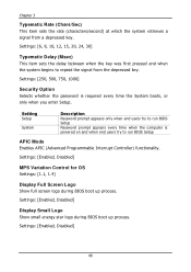
... On Off Description Forces keypad to behave as 10-key Forces keypad to boot from alternate devices if the system fails to behave as BIOS attempts to load the disk operating system. Settings: [Enabled, Disabled] 39 Setting Enabled Disabled Description Enable alternate boot device No alternate boot... drive Disable the boot device sequence Boot Other Device Enables the system to boot from the "First/Second/Third Boot Device" list. BIOS Setup First/Second/Third Boot Device Set the boot device sequence as arrow keys Typematic Rate Setting Enables "Typematic Rate" and "Typematic Delay"...
... On Off Description Forces keypad to behave as 10-key Forces keypad to boot from alternate devices if the system fails to behave as BIOS attempts to load the disk operating system. Settings: [Enabled, Disabled] 39 Setting Enabled Disabled Description Enable alternate boot device No alternate boot... drive Disable the boot device sequence Boot Other Device Enables the system to boot from the "First/Second/Third Boot Device" list. BIOS Setup First/Second/Third Boot Device Set the boot device sequence as arrow keys Typematic Rate Setting Enables "Typematic Rate" and "Typematic Delay"...
User Manual
Page 48
...is required every time the System boots, or only when you enter Setup. Settings: [Enabled, Disabled] Display Small Logo Show small energy star logo during BIOS boot up process. Settings: [6, 8, 10, 12, 15, 20, 24, 30] Typematic Delay (Msec) This item sets the delay between when ...the key was first pressed and when the system begins to run BIOS Setup APIC Mode Enables APIC (Advanced Programmable Interrupt Controller) functionality. Settings: [250, 500, 750, 1000] Security Option Selects whether the password is ...
...is required every time the System boots, or only when you enter Setup. Settings: [Enabled, Disabled] Display Small Logo Show small energy star logo during BIOS boot up process. Settings: [6, 8, 10, 12, 15, 20, 24, 30] Typematic Delay (Msec) This item sets the delay between when ...the key was first pressed and when the system begins to run BIOS Setup APIC Mode Enables APIC (Advanced Programmable Interrupt Controller) functionality. Settings: [250, 500, 750, 1000] Security Option Selects whether the password is ...

User Manual
Page 49
... throttled performance that will be initiated when the on die sensor goes from overheat. CPU FEATURE BIOS Setup Phoenix - AwardBIOS CMOS Setup Utility CPU Feature Thermal Management TM2 Bus Ratio TM2 Bus VID VIA V4 Fast TRDY VIA V4 Sparse Writes C7 Thermal Monitor C7 CMPXCHG8 C7 NoExecute (NX) C7 TM1/TM2 Working...
... throttled performance that will be initiated when the on die sensor goes from overheat. CPU FEATURE BIOS Setup Phoenix - AwardBIOS CMOS Setup Utility CPU Feature Thermal Management TM2 Bus Ratio TM2 Bus VID VIA V4 Fast TRDY VIA V4 Sparse Writes C7 Thermal Monitor C7 CMPXCHG8 C7 NoExecute (NX) C7 TM1/TM2 Working...

User Manual
Page 51
C7 TM Overstress Temp ºC Key in a DEC number. Settings: [Enabled, Disabled] ACPI C4 Function Enables the ACPI (Advanced Configuration and Power Management Interface) C4 functionality. Settings: [Min = 0, Max = 255] BIOS Setup ODCM Enables the ODCM (On Demand Clock Modulation) functionality. Settings: [Enabled, Disabled] 43
C7 TM Overstress Temp ºC Key in a DEC number. Settings: [Enabled, Disabled] ACPI C4 Function Enables the ACPI (Advanced Configuration and Power Management Interface) C4 functionality. Settings: [Min = 0, Max = 255] BIOS Setup ODCM Enables the ODCM (On Demand Clock Modulation) functionality. Settings: [Enabled, Disabled] 43

User Manual
Page 53
...] [Press Enter] Item Help Menu Level If there are familiar with the system. Display Card Priority This setting specifies which VGA card is used for BIOS to select which one to boot : Move Enter: Select F5: Previous Values +/-/PU/PD: Value F10: Save F6: Fail-Safe Defaults ESC: Exit F1: General... item is used with the chipset. Settings: [CRT, LCD, CRT + LCD, TV, CRT + TV, LCD + TV, DVI, CRT + DVI, TV + DVI] 45 ADVANCED CHIPSET FEATURES BIOS Setup Phoenix -
...] [Press Enter] Item Help Menu Level If there are familiar with the system. Display Card Priority This setting specifies which VGA card is used for BIOS to select which one to boot : Move Enter: Select F5: Previous Values +/-/PU/PD: Value F10: Save F6: Fail-Safe Defaults ESC: Exit F1: General... item is used with the chipset. Settings: [CRT, LCD, CRT + LCD, TV, CRT + TV, LCD + TV, DVI, CRT + DVI, TV + DVI] 45 ADVANCED CHIPSET FEATURES BIOS Setup Phoenix -