
User Manual
Page 3
... RESEAU. This equipment generates, uses and can radiate radio frequency energy and, if not installed and used in order to comply with the emission limits. VIA EPIA Mini-ITX Mainboard Tested to operate the equipment. power cord, if any, must be required to correct the interference at his own expense. These limits are designed...
... RESEAU. This equipment generates, uses and can radiate radio frequency energy and, if not installed and used in order to comply with the emission limits. VIA EPIA Mini-ITX Mainboard Tested to operate the equipment. power cord, if any, must be required to correct the interference at his own expense. These limits are designed...

User Manual
Page 5
Box Contents This VIA EPIA Mini-ITX Mainboard package should contain the following items: • 1 x VIA EPIA Mini-ITX Mainboard • 1 x User's manual • 1 x ATA-33/66/100 Hard drive ribbon cables • 1 x Driver Utilities CD • 1 x I/O Bracket v
Box Contents This VIA EPIA Mini-ITX Mainboard package should contain the following items: • 1 x VIA EPIA Mini-ITX Mainboard • 1 x User's manual • 1 x ATA-33/66/100 Hard drive ribbon cables • 1 x Driver Utilities CD • 1 x I/O Bracket v

User Manual
Page 8
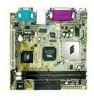
...: Mainboard Specifications 1-2 Mainboard Layout 1-4 Components Guide 1-5 1-1 Specifications The ultra-compact and highly intergrated VIA EPIA Mini-ITX Mainboard is the smallest form factor mainboard specification available today, developed by VIA Technologies, Inc as part of the FlexATX mainboard form factor. The VIA EPIA Mini-ITX mainboard enables the creation of an exciting new generation of small, ergonomic, innovative and...
...: Mainboard Specifications 1-2 Mainboard Layout 1-4 Components Guide 1-5 1-1 Specifications The ultra-compact and highly intergrated VIA EPIA Mini-ITX Mainboard is the smallest form factor mainboard specification available today, developed by VIA Technologies, Inc as part of the FlexATX mainboard form factor. The VIA EPIA Mini-ITX mainboard enables the creation of an exciting new generation of small, ergonomic, innovative and...

User Manual
Page 11
Chapter 1 Layout VIA EPIA Mini-ITX Mainboard (Note: Onboard DOC is optional) 1-4
Chapter 1 Layout VIA EPIA Mini-ITX Mainboard (Note: Onboard DOC is optional) 1-4
User Manual
Page 14
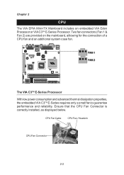
... The VIA EPIA Mini-ITX Mainboard includes an embedded VIA Eden Processor or VIA C3TM E-Series Processor. Two fan connectors (Fan 1 & Fan 2) are provided on the mainboard, alllowing for the connection of a CPU fan and an additional system case fan. The VIA C3TM E-Series Processor With low power consumption and advanced thermal dissipation properties, the embedded VIA C3TM...
... The VIA EPIA Mini-ITX Mainboard includes an embedded VIA Eden Processor or VIA C3TM E-Series Processor. Two fan connectors (Fan 1 & Fan 2) are provided on the mainboard, alllowing for the connection of a CPU fan and an additional system case fan. The VIA C3TM E-Series Processor With low power consumption and advanced thermal dissipation properties, the embedded VIA C3TM...

User Manual
Page 16
... properly, at either end of the DIMM slot outwards. 2.) Align the SDRAM module with the corresponding notches on the DIMM slot. Chapter 2 Memory Installation The VIA EPIA Mini-ITX Mainboard provides two 168-pin DIMM slots for PC 100/133 SDRAM memory modules.
... properly, at either end of the DIMM slot outwards. 2.) Align the SDRAM module with the corresponding notches on the DIMM slot. Chapter 2 Memory Installation The VIA EPIA Mini-ITX Mainboard provides two 168-pin DIMM slots for PC 100/133 SDRAM memory modules.
User Manual
Page 17
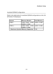
Socket Memory Module Total Mem ory DIMM 1 DIMM 2 32MB, 64MB, 128MB, 32MB~512MB 256MB, 512MB 32MB, 64MB, 128MB, 32MB~512MB 256MB, 512MB Maximum System Memory Supported 1GB 2-5 Hardware Setup Available SDRAM Configurations Refer to the table below for available SDRAM configurations on the VIA EPIA Mini-ITX Mainboard.
Socket Memory Module Total Mem ory DIMM 1 DIMM 2 32MB, 64MB, 128MB, 32MB~512MB 256MB, 512MB 32MB, 64MB, 128MB, 32MB~512MB 256MB, 512MB Maximum System Memory Supported 1GB 2-5 Hardware Setup Available SDRAM Configurations Refer to the table below for available SDRAM configurations on the VIA EPIA Mini-ITX Mainboard.

User Manual
Page 18
Chapter 2 Power Supply The VIA EPIA Mini-ITX Mainboard requires an ATX power supply to ensure that no damage will be connected. Then, push down the power supply plug firmly into the connector. 2-6 Before inserting the power supply connector, always make sure the plugs of the power supply are inserted in the proper orientation and the pins are installed correctly to be caused. ATX 20-Pin Power Connector To connect the ATX power supply, make sure that all components are correctly aligned.
Chapter 2 Power Supply The VIA EPIA Mini-ITX Mainboard requires an ATX power supply to ensure that no damage will be connected. Then, push down the power supply plug firmly into the connector. 2-6 Before inserting the power supply connector, always make sure the plugs of the power supply are inserted in the proper orientation and the pins are installed correctly to be caused. ATX 20-Pin Power Connector To connect the ATX power supply, make sure that all components are correctly aligned.

User Manual
Page 19
... Port The mainboard provides a standard RJ-45 port for connection to this standard PS/2 mouse connector. Hardware Setup Back Panel The back panel of the VIA EPIA Mini-ITX Mainboard contains the following connectors: PS/2 Mouse LPT Connector RJ-45 Port COM Port PS/2 Keyboard S-Video Port USB Ports Line Line Mic CRT Connector...
... Port The mainboard provides a standard RJ-45 port for connection to this standard PS/2 mouse connector. Hardware Setup Back Panel The back panel of the VIA EPIA Mini-ITX Mainboard contains the following connectors: PS/2 Mouse LPT Connector RJ-45 Port COM Port PS/2 Keyboard S-Video Port USB Ports Line Line Mic CRT Connector...
User Manual
Page 21
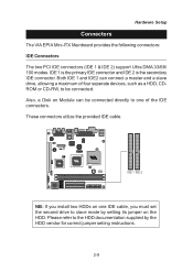
... on Module can connect a master and a slave drive, allowing a maximum of the IDE connectors. Both IDE 1 and IDE2 can be connected. Hardware Setup Connectors The VIA EPIA Mini-ITX Mainboard provides the following connectors: IDE Connectors The two PCI IDE connectors (IDE 1 & IDE 2) support Ultra DMA 33/66/ 100 modes. IDE 1 IDE 2 NB: If...
... on Module can connect a master and a slave drive, allowing a maximum of the IDE connectors. Both IDE 1 and IDE2 can be connected. Hardware Setup Connectors The VIA EPIA Mini-ITX Mainboard provides the following connectors: IDE Connectors The two PCI IDE connectors (IDE 1 & IDE 2) support Ultra DMA 33/66/ 100 modes. IDE 1 IDE 2 NB: If...

User Manual
Page 26
This section explains the functions of system parameter settings. Chapter 2 Jumpers The VIA EPIA Mini-ITX Mainboard provides a series of jumpers to clear the CMOS memory of all the mainboard settings. Clear CMOS (J10) The Clear CMOS jumper allows you want ...
This section explains the functions of system parameter settings. Chapter 2 Jumpers The VIA EPIA Mini-ITX Mainboard provides a series of jumpers to clear the CMOS memory of all the mainboard settings. Clear CMOS (J10) The Clear CMOS jumper allows you want ...