
English Owner's Manual
Page 4
... INFORMATION 2 PRECAUTIONS 2 Warning 2 THE FCC WANTS YOU TO KNOW 3 Scanning Legally 7 ABOUT YOUR NEW BC355N SCANNER 8 FEATURE SUMMARY 9 Band Plans 11 USA Band Plan 11 Canada Band Plan 13 INCLUDED IN YOUR SCANNER PACKAGE 16 Optional Accessories 16 INSTALLING THE BC355N SCANNER 17 FOR HOME USE (DESKTOP INSTALLATION 17 For Mobile Use (In-Car Installation 18...
... INFORMATION 2 PRECAUTIONS 2 Warning 2 THE FCC WANTS YOU TO KNOW 3 Scanning Legally 7 ABOUT YOUR NEW BC355N SCANNER 8 FEATURE SUMMARY 9 Band Plans 11 USA Band Plan 11 Canada Band Plan 13 INCLUDED IN YOUR SCANNER PACKAGE 16 Optional Accessories 16 INSTALLING THE BC355N SCANNER 17 FOR HOME USE (DESKTOP INSTALLATION 17 For Mobile Use (In-Car Installation 18...

English Owner's Manual
Page 16
...; DC Power Cord for your BC355N are missing or damaged, immediately contact your scanner. • Bracket • Screw • This Owner's Manual • Other Printed Materials If any of purchase or Uniden Customer Hotline at: 1-800-2971023 during regular business hours Monday through Friday. Optional Accessories The following optional accessories for hard-wiring power from...
...; DC Power Cord for your BC355N are missing or damaged, immediately contact your scanner. • Bracket • Screw • This Owner's Manual • Other Printed Materials If any of purchase or Uniden Customer Hotline at: 1-800-2971023 during regular business hours Monday through Friday. Optional Accessories The following optional accessories for hard-wiring power from...
English Owner's Manual
Page 18
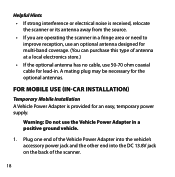
Plug one end of the Vehicle Power Adapter into the vehicle's accessory power jack and the other end into the DC 13.8V jack ...Car Installation) Temporary Mobile Installation A Vehicle Power Adapter is received, relocate the scanner or its antenna away from the source. • If you are operating the scanner in a fringe area or need to improve reception, use an optional antenna ...designed for multi-band coverage. (You can purchase this type of the scanner. 18 A mating plug may be necessary for an easy, temporary power supply. Warning: Do not use 50...
Plug one end of the Vehicle Power Adapter into the vehicle's accessory power jack and the other end into the DC 13.8V jack ...Car Installation) Temporary Mobile Installation A Vehicle Power Adapter is received, relocate the scanner or its antenna away from the source. • If you are operating the scanner in a fringe area or need to improve reception, use an optional antenna ...designed for multi-band coverage. (You can purchase this type of the scanner. 18 A mating plug may be necessary for an easy, temporary power supply. Warning: Do not use 50...
English Owner's Manual
Page 20
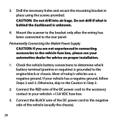
... chassis. Connect the BLACK wire of the DC power cord to the rear panel. Drill the necessary holes and secure the mounting bracket in connecting accessories to the Caution in your vehicle has a negative ground, follow Steps 2 and 3. Permanently Connecting the Mobile Power Supply CAUTION: If you are ... the vehicle fuse box, please see your automotive dealer for advice on proper installation. 1. If your vehicle's +13.8 VDC fuse box. 3. Mount the scanner to the bracket only after the wiring has been connected to the negative side of the vehicle (usually the chassis). 20
... chassis. Connect the BLACK wire of the DC power cord to the rear panel. Drill the necessary holes and secure the mounting bracket in connecting accessories to the Caution in your vehicle has a negative ground, follow Steps 2 and 3. Permanently Connecting the Mobile Power Supply CAUTION: If you are ... the vehicle fuse box, please see your automotive dealer for advice on proper installation. 1. If your vehicle's +13.8 VDC fuse box. 3. Mount the scanner to the bracket only after the wiring has been connected to the negative side of the vehicle (usually the chassis). 20
English Owner's Manual
Page 21
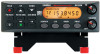
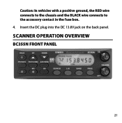
Caution: In vehicles with a positive ground, the RED wire connects to the chassis and the BLACK wire connects to the accessory contact in the fuse box. 4. SCANNER OPERATION OVERVIEW BC355N Front Panel 21 Insert the DC plug into the DC 13.8V jack on the back panel.
Caution: In vehicles with a positive ground, the RED wire connects to the chassis and the BLACK wire connects to the accessory contact in the fuse box. 4. SCANNER OPERATION OVERVIEW BC355N Front Panel 21 Insert the DC plug into the DC 13.8V jack on the back panel.

English Owner's Manual
Page 58
You could be using an outlet controlled by the wall switch. Make sure the ignition key in your room. TROUBLESHOOTING GUIDE PROBLEM Scanner won't work SOLUTION Try one of these options: • Check the connections at both ends of your vehicle is in the Accessory position. • Make sure the power switch is blown. Move the AC adapter to another wall outlet. • Check the connections at both ends of the DC cord or Vehicle Power Adapter. • Check to see if the fuse is turned on the wall switch of the AC adapter. • Turn on . 58
You could be using an outlet controlled by the wall switch. Make sure the ignition key in your room. TROUBLESHOOTING GUIDE PROBLEM Scanner won't work SOLUTION Try one of these options: • Check the connections at both ends of your vehicle is in the Accessory position. • Make sure the power switch is blown. Move the AC adapter to another wall outlet. • Check the connections at both ends of the DC cord or Vehicle Power Adapter. • Check to see if the fuse is turned on the wall switch of the AC adapter. • Turn on . 58


