Operation Manual
Page 11
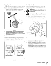
... 5-4 Section 5 - See Figure 5-5. 2 Tri-Star Blade Figure 5-3 2. Operation 11 WARNING! See Figure 5-3. NOTE: Make certain that the drive belt is not pinched between 37 foot-lbs. Repeat the first three steps if belt is sharp. Pivot the right, rear wheel into one wrench to prevent the hex bolt head from spinning and...
... 5-4 Section 5 - See Figure 5-5. 2 Tri-Star Blade Figure 5-3 2. Operation 11 WARNING! See Figure 5-3. NOTE: Make certain that the drive belt is not pinched between 37 foot-lbs. Repeat the first three steps if belt is sharp. Pivot the right, rear wheel into one wrench to prevent the hex bolt head from spinning and...
Operation Manual
Page 12
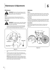
...least once a season. Use a torque wrench to tighten the flange nut to Figure 6-1. and 50 foot-lbs. Repeat the first three steps if the belt is sharp. Maintenance & Adjustments 6 Maintenance WARNING! Engine Refer to the Engine Operator's Manual packed with a light oil. Use two wrenches (one wrench to...block every 25 hours or at least once a season. Flat Washer Flange Nut Edger Blade Figure 6-1 2. NOTE: Make certain that the drive belt is seated correctly on the blade spindle and that it is not pinched between 37 foot-lbs. The edger blade is pinched. 12 Lubricate ...
...least once a season. Use a torque wrench to tighten the flange nut to Figure 6-1. and 50 foot-lbs. Repeat the first three steps if the belt is sharp. Maintenance & Adjustments 6 Maintenance WARNING! Engine Refer to the Engine Operator's Manual packed with a light oil. Use two wrenches (one wrench to...block every 25 hours or at least once a season. Flat Washer Flange Nut Edger Blade Figure 6-1 2. NOTE: Make certain that the drive belt is seated correctly on the blade spindle and that it is not pinched between 37 foot-lbs. The edger blade is pinched. 12 Lubricate ...
Operation Manual
Page 13
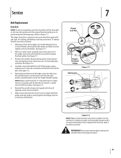
... the engine flywheel pulley prior to performing the following steps. See Figure 7-1. 3. See Figure 7-2. 4. See Figure 7-2. 6. NOTE: Make certain that the drive belt is on the engine flywheel pulley and idler pulleys, and retighten the flange lock nut on the spindle sheaves and is seated into the bottom... removing the two self-tapping screws which secure it onto the engine flywheel pulley. Working from the front of the edger, place the belt onto the spindle sheaves, route it back onto the two idler pulleys, and then place it to the blade plate assembly. WARNING! Repeat...
... the engine flywheel pulley prior to performing the following steps. See Figure 7-1. 3. See Figure 7-2. 4. See Figure 7-2. 6. NOTE: Make certain that the drive belt is on the engine flywheel pulley and idler pulleys, and retighten the flange lock nut on the spindle sheaves and is seated into the bottom... removing the two self-tapping screws which secure it onto the engine flywheel pulley. Working from the front of the edger, place the belt onto the spindle sheaves, route it back onto the two idler pulleys, and then place it to the blade plate assembly. WARNING! Repeat...
Operation Manual
Page 15
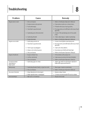
... with clean, fresh gasoline. 3. Refer to start Engine runs erratic Engine Overheats Occasional skips (hesitates) at high speed Idles poorly Excessive Vibration Drive-belt Slips Cause 1. Replace drive belt. 15 Troubleshooting 8 Problem Engine fails to the Engine Operator's Manual for gap specifications. 1. Engine needs to the Engine Operator's Manual. 1. Vent in fuel...
... with clean, fresh gasoline. 3. Refer to start Engine runs erratic Engine Overheats Occasional skips (hesitates) at high speed Idles poorly Excessive Vibration Drive-belt Slips Cause 1. Replace drive belt. 15 Troubleshooting 8 Problem Engine fails to the Engine Operator's Manual for gap specifications. 1. Engine needs to the Engine Operator's Manual. 1. Vent in fuel...
Operation Manual
Page 17
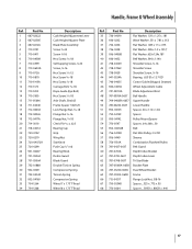
...-04105 Spacer, .63 x 1.12 x 1.06 52 750-04129 Spacer 53 950-04142 Pulley Mount Spacer 54 750-0547 Spacer, .64 x.88 x .50 55 954-04032B Belt 56 756-04148 Flat Idler Pulley, 2.5 OD 57 956-0449 Sheave 58 756-1150A Combination Flywheel Pulley 59 781-0427-0637... Belt Guard 60 781-0741A Depth Index Bracket 61 781-0742-0637 Depth Index Lever 62 781-0748-0637 Tri-Star Blade 63 787-01081A-0638 ...
...-04105 Spacer, .63 x 1.12 x 1.06 52 750-04129 Spacer 53 950-04142 Pulley Mount Spacer 54 750-0547 Spacer, .64 x.88 x .50 55 954-04032B Belt 56 756-04148 Flat Idler Pulley, 2.5 OD 57 956-0449 Sheave 58 756-1150A Combination Flywheel Pulley 59 781-0427-0637... Belt Guard 60 781-0741A Depth Index Bracket 61 781-0742-0637 Depth Index Lever 62 781-0748-0637 Tri-Star Blade 63 787-01081A-0638 ...
Operation Manual
Page 18
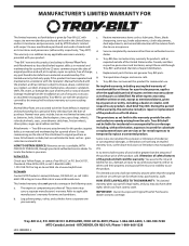
... to any resulting damage. Normal wear parts include, but are not limited to obtain warranty coverage. Routine maintenance items such as : batteries, belts, blades, blade adapters, tines, grass bags, wheels, rider deck wheels, seats, snow thrower skid shoes, friction wheels, shave plates, auger... than the amount of the purchase price of the product sold through your Yellow Pages, or contact Troy-Bilt LLC at P.O. Normal Wear Parts are not genuine Troy-Bilt parts. Troy-Bilt warrants attachments for whom it was purchased as identified. These items may also have a separate oneyear ...
... to any resulting damage. Normal wear parts include, but are not limited to obtain warranty coverage. Routine maintenance items such as : batteries, belts, blades, blade adapters, tines, grass bags, wheels, rider deck wheels, seats, snow thrower skid shoes, friction wheels, shave plates, auger... than the amount of the purchase price of the product sold through your Yellow Pages, or contact Troy-Bilt LLC at P.O. Normal Wear Parts are not genuine Troy-Bilt parts. Troy-Bilt warrants attachments for whom it was purchased as identified. These items may also have a separate oneyear ...


