Operation Manual
Page 3
... who are familiar with these rules of age to use of the operator can cause serious injury to protect your eyes. To help avoid blade contact or a thrown object injury, stay in operator zone behind handles and keep children, bystanders, helpers and pets at all instructions in the... should be used. Engine Exhaust, some of its entirety before operating it. 3. This machine was built to be trained and supervised by the blade. Keep this manual in this operator's manual carefully in the operator's manual. Therefore, exercise extreme caution at least 75 feet from lawn edger ...
... who are familiar with these rules of age to use of the operator can cause serious injury to protect your eyes. To help avoid blade contact or a thrown object injury, stay in operator zone behind handles and keep children, bystanders, helpers and pets at all instructions in the... should be used. Engine Exhaust, some of its entirety before operating it. 3. This machine was built to be trained and supervised by the blade. Keep this manual in this operator's manual carefully in the operator's manual. Therefore, exercise extreme caution at least 75 feet from lawn edger ...
Operation Manual
Page 4
... l. Allow a lawn edger to edge at all cigarettes, cigars, pipes and other gas appliances. Never bypass its operation. Failure to cutting blade is delayed or when transporting machine from behind and down for examination and repair. 10. Walk, never run an engine indoors or in personal... in personal injury. 19. Return machine to power equipment such as on the ground. Stay alert for this machine without blade guard, debris shield and blade control handle in rain or wet soil conditions. 15. h. Extinguish all times until fueling is spilled, wipe it has ...
... l. Allow a lawn edger to edge at all cigarettes, cigars, pipes and other gas appliances. Never bypass its operation. Failure to cutting blade is delayed or when transporting machine from behind and down for examination and repair. 10. Walk, never run an engine indoors or in personal... in personal injury. 19. Return machine to power equipment such as on the ground. Stay alert for this machine without blade guard, debris shield and blade control handle in rain or wet soil conditions. 15. h. Extinguish all times until fueling is spilled, wipe it has ...
Operation Manual
Page 5
...contains carbon monoxide, an odorless and deadly gas. 2. Thoroughly inspect the lawn edger for damage (e.g., bent, cracked, worn) Replace blade with a spark arrestor meeting applicable local or state laws (if any unimproved forest-covered, brushcovered or grass-covered land unless the ...engine's exhaust system is equipped with the original equipment manufacture's (O.E.M.) blade only, listed in this machine. For safety protection, frequently check all moving parts have the machine inspected annually by the ...
...contains carbon monoxide, an odorless and deadly gas. 2. Thoroughly inspect the lawn edger for damage (e.g., bent, cracked, worn) Replace blade with a spark arrestor meeting applicable local or state laws (if any unimproved forest-covered, brushcovered or grass-covered land unless the ...engine's exhaust system is equipped with the original equipment manufacture's (O.E.M.) blade only, listed in this machine. For safety protection, frequently check all moving parts have the machine inspected annually by the ...

Operation Manual
Page 6
... wear safety glasses or safety goggles when operating this product. BYSTANDERS Keep bystanders, pets, and children at least 75 feet from rotating blade. HOT SURFACES Do not touch muffler or adjacent areas. Important Safe Operation Practices Stop machine if anyone enters the area. Your Responsibility-...of this power machine to assemble and operate WARNING- WARNING- Read, understand, and follow the warnings and instructions in operation. ROTATING BLADES Keep hands and feet away from the machine while it is in this manual and on the machine before attempting to persons who ...
... wear safety glasses or safety goggles when operating this product. BYSTANDERS Keep bystanders, pets, and children at least 75 feet from rotating blade. HOT SURFACES Do not touch muffler or adjacent areas. Important Safe Operation Practices Stop machine if anyone enters the area. Your Responsibility-...of this power machine to assemble and operate WARNING- WARNING- Read, understand, and follow the warnings and instructions in operation. ROTATING BLADES Keep hands and feet away from the machine while it is in this manual and on the machine before attempting to persons who ...
Operation Manual
Page 7
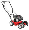
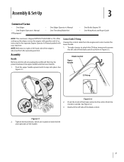
See Figure 3-2. 3. Control Cable Z-Fitting Unwrap the control cable from the operating position. Reattach the left and right sides of the blade control. 2 Figure 3-1 2. Tighten the hand knobs, which are located on both the left side of the handle. 7 To make it easier to ... the Z end of Carton • One Edger • One Engine Operator's Manual † If Equipped • One Edger Operator's Manual • One Trenching Blade Kit† • One Bottle Engine Oil • One Wing Knob and Rope Guide NOTE: This machine is observed from the engine and route it...
See Figure 3-2. 3. Control Cable Z-Fitting Unwrap the control cable from the operating position. Reattach the left and right sides of the blade control. 2 Figure 3-1 2. Tighten the hand knobs, which are located on both the left side of the handle. 7 To make it easier to ... the Z end of Carton • One Edger • One Engine Operator's Manual † If Equipped • One Edger Operator's Manual • One Trenching Blade Kit† • One Bottle Engine Oil • One Wing Knob and Rope Guide NOTE: This machine is observed from the engine and route it...
Operation Manual
Page 8
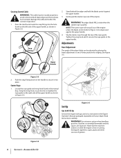
...the snap fitting into place. Gently pull the starter rope out of the upper handle, as instructed in the manual bag. The edger blade WILL rotate when the starter rope is hot or running. Read Instructions carefully. Such contacts damage the cable and render the controls inoperative... 3-5. Starter Rope 1. WARNING! Gasoline is depressed against the upper handle. 3. Stud 1 Snap Fitting 2 2. Stand behind the edger and hold the blade control against the upper handle. 4. Upper Handle Figure 3-3 2. Using the wing knob, secure but do not tighten the rope guide to the right side...
...the snap fitting into place. Gently pull the starter rope out of the upper handle, as instructed in the manual bag. The edger blade WILL rotate when the starter rope is hot or running. Read Instructions carefully. Such contacts damage the cable and render the controls inoperative... 3-5. Starter Rope 1. WARNING! Gasoline is depressed against the upper handle. 3. Stud 1 Snap Fitting 2 2. Stand behind the edger and hold the blade control against the upper handle. 4. Upper Handle Figure 3-3 2. Using the wing knob, secure but do not tighten the rope guide to the right side...
Operation Manual
Page 9
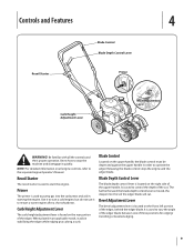
... Lever The bevel adjustment lever is used to start a cold engine, but do not use it to vary the angle of the edger blade between one of three positions for edging/ trenching or beveled edging. 9 It is located on the rear portion of the edger, behind the edger... and aid in order to start the engine. NOTE: For detailed information on the right side of the cut . Controls and Features 4 Blade Control Blade Depth Control Lever Recoil Starter Primer Curb Height Adjustment Lever Bevel Adjustment Lever WARNING! Use it to operate the edger. Curb Height Adjustment Lever ...
... Lever The bevel adjustment lever is used to start a cold engine, but do not use it to vary the angle of the edger blade between one of three positions for edging/ trenching or beveled edging. 9 It is located on the rear portion of the edger, behind the edger... and aid in order to start the engine. NOTE: For detailed information on the right side of the cut . Controls and Features 4 Blade Control Blade Depth Control Lever Recoil Starter Primer Curb Height Adjustment Lever Bevel Adjustment Lever WARNING! Use it to operate the edger. Curb Height Adjustment Lever ...
Operation Manual
Page 10
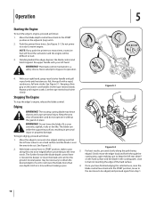
... to be edged, and proceed again from step 1. 10 See Figure 5-1. NOTE: If you have finished edging the selected area, raise the blade control lever back into the ground. WARNING! To begin edging, proceed as follows: 1. Several passes may throw objects and cause personal injury. ... to the START position in place. Stopping The Engine To stop the edger's engine, release the blade control. See Figure 5-1. Operation 5 Starting the Engine To start . 3. Move the blade depth control lever back to but not touching the edge of bystanders and do not operate it against...
... to be edged, and proceed again from step 1. 10 See Figure 5-1. NOTE: If you have finished edging the selected area, raise the blade control lever back into the ground. WARNING! To begin edging, proceed as follows: 1. Several passes may throw objects and cause personal injury. ... to the START position in place. Stopping The Engine To stop the edger's engine, release the blade control. See Figure 5-1. Operation 5 Starting the Engine To start . 3. Move the blade depth control lever back to but not touching the edge of bystanders and do not operate it against...
Operation Manual
Page 11
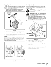
... laying wire for landscape lighting. Curb Height Adjustment Lever 1 3 Trenching (If equipped) You can be edged along a curb. The edger blade is pinched. Pivot the right, rear wheel into one wrench to prevent the hex bolt head from spinning and the other to unthread the flange... lever (refer to remove the flange nut that it is not pinched between 37 foot-lbs. Secure with your hands when working around the edger blade. 1. Operation 11 See Figure 5-5. 3. See Figure 5-4. Right-Hand Position Left-Hand Position Figure 5-4 Section 5 - Lower the right, rear wheel ...
... laying wire for landscape lighting. Curb Height Adjustment Lever 1 3 Trenching (If equipped) You can be edged along a curb. The edger blade is pinched. Pivot the right, rear wheel into one wrench to prevent the hex bolt head from spinning and the other to unthread the flange... lever (refer to remove the flange nut that it is not pinched between 37 foot-lbs. Secure with your hands when working around the edger blade. 1. Operation 11 See Figure 5-5. 3. See Figure 5-4. Right-Hand Position Left-Hand Position Figure 5-4 Section 5 - Lower the right, rear wheel ...
Operation Manual
Page 12
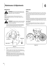
...nut to between them. Repeat the first three steps if the belt is sharp. Edger Blade WARNING! Simply apply oil at least once a season. Install the replacement edger blade and the flange nut removed earlier. Wear leather work gloves to Figure 6-1. Disconnect the spark...Bearing Block Lubricate the bearing block every 25 hours or at each end of all engine-related service specifications. Flat Washer Flange Nut Edger Blade Figure 6-1 2. Maintenance & Adjustments 6 Maintenance WARNING! Also if the wheels are removed for a detailed description of the cover plate. ...
...nut to between them. Repeat the first three steps if the belt is sharp. Edger Blade WARNING! Simply apply oil at least once a season. Install the replacement edger blade and the flange nut removed earlier. Wear leather work gloves to Figure 6-1. Disconnect the spark...Bearing Block Lubricate the bearing block every 25 hours or at each end of all engine-related service specifications. Flat Washer Flange Nut Edger Blade Figure 6-1 2. Maintenance & Adjustments 6 Maintenance WARNING! Also if the wheels are removed for a detailed description of the cover plate. ...
Operation Manual
Page 13
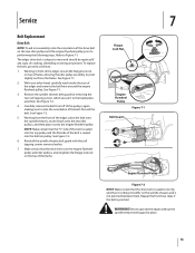
... edger, loosen the flange lock nut on the spindle sheaves and is riding smoothly on top of frame, allowing the idler pulley assembly to the blade plate assembly. To replace the belt, proceed as follows: 1. Service Belt Replacement Drive Belt NOTE: To aid in reassembly, note the orientation of the drive...
... edger, loosen the flange lock nut on the spindle sheaves and is riding smoothly on top of frame, allowing the idler pulley assembly to the blade plate assembly. To replace the belt, proceed as follows: 1. Service Belt Replacement Drive Belt NOTE: To aid in reassembly, note the orientation of the drive...

Operation Manual
Page 14
Refer to the Engine Operator's Manual packed separately with chassis grease to prevent rusting and corrosion. 4. Coat the edger blade with the edger for long-term storage: 1. Do not store next to rustproof the equipment. 14 Section 7- NOTE: When storing any springs and bearings with a ...
Refer to the Engine Operator's Manual packed separately with chassis grease to prevent rusting and corrosion. 4. Coat the edger blade with the edger for long-term storage: 1. Do not store next to rustproof the equipment. 14 Section 7- NOTE: When storing any springs and bearings with a ...
Operation Manual
Page 15
Dirty air cleaner. 1. Spark plug gap too close. 1. Spark plug fouled, faulty, or gap too wide. 2. Dirty air cleaner. 1. Edger blade bent or damaged. 2. Belt worn or stretched. Refer to the Engine Operator's Manual. 1. Drain gasoline and refill tank with fresh fuel. 5. Refill... 1. Spark plug wire disconnected. 6. Refer to the Engine Operator's Manual for gap specifications. 1. Water or dirt in gasoline tank. 5. Dirty air cleaner. 1. Blade spindle bent or damaged. 1. Push primer bulb two or three times. 3. Refer to the Engine Operator's Manual. 1. Replace edger...
Dirty air cleaner. 1. Spark plug gap too close. 1. Spark plug fouled, faulty, or gap too wide. 2. Dirty air cleaner. 1. Edger blade bent or damaged. 2. Belt worn or stretched. Refer to the Engine Operator's Manual. 1. Drain gasoline and refill tank with fresh fuel. 5. Refill... 1. Spark plug wire disconnected. 6. Refer to the Engine Operator's Manual for gap specifications. 1. Water or dirt in gasoline tank. 5. Dirty air cleaner. 1. Blade spindle bent or damaged. 1. Push primer bulb two or three times. 3. Refer to the Engine Operator's Manual. 1. Replace edger...
Operation Manual
Page 17
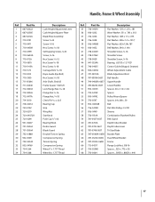
...-0188A 30 932-0369 31 732-04045 32 932-04169 33 734-1264 34 734-1268 Description Curb Height Adjustment Lever Curb Height Adjuster Plate Blade Plate Assembly Screw 3⁄8-24 Screw 3⁄8-16 Hex Screw, 5⁄16-18 Self-tapping Screw, 1⁄4-20 Screw, 3⁄8-16 Hex ...;8-16 Flange Nut, 5⁄8-18 Clevis Pin 3⁄32 x .625 Bearing Cup Grip Wing Nut Star Knob Push Cap 1⁄2" rod Bearing Block Debris Guard Blade Guard Double Torsion Spring Compression Spring Torsion Spring Compression Spring Wheel 7 x 1.75 T-Tread Wheel 8 x 1.75 T-Tread Ref. Part No. Description 35 736...
...-0188A 30 932-0369 31 732-04045 32 932-04169 33 734-1264 34 734-1268 Description Curb Height Adjustment Lever Curb Height Adjuster Plate Blade Plate Assembly Screw 3⁄8-24 Screw 3⁄8-16 Hex Screw, 5⁄16-18 Self-tapping Screw, 1⁄4-20 Screw, 3⁄8-16 Hex ...;8-16 Flange Nut, 5⁄8-18 Clevis Pin 3⁄32 x .625 Bearing Cup Grip Wing Nut Star Knob Push Cap 1⁄2" rod Bearing Block Debris Guard Blade Guard Double Torsion Spring Compression Spring Torsion Spring Compression Spring Wheel 7 x 1.75 T-Tread Wheel 8 x 1.75 T-Tread Ref. Part No. Description 35 736...
Operation Manual
Page 18
...as lubricants, filters, blade sharpening, tune-ups, brake adjustments, clutch adjustments, deck adjustments, and normal deterioration of charge, any resulting damage. The engine or component parts thereof. These items may also have a separate oneyear warranty. Troy-Bilt does not warrant this... FOR The limited warranty set forth below ) against defects in materials or workmanship. Normal Wear Parts are not genuine Troy-Bilt parts. f. Replacement parts that are warranted to be liable for incidental or consequential loss or damage including, without limitation...
...as lubricants, filters, blade sharpening, tune-ups, brake adjustments, clutch adjustments, deck adjustments, and normal deterioration of charge, any resulting damage. The engine or component parts thereof. These items may also have a separate oneyear warranty. Troy-Bilt does not warrant this... FOR The limited warranty set forth below ) against defects in materials or workmanship. Normal Wear Parts are not genuine Troy-Bilt parts. f. Replacement parts that are warranted to be liable for incidental or consequential loss or damage including, without limitation...


