Operation Manual
Page 2
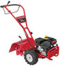
... be necessary, should you have difficulty assembling this product or have any questions regarding the controls, operation, or maintenance of product specifications for purchasing a Troy-Bilt Tiller. Model Number Serial Number Customer Support Please do so could result in the provided area to Maintenance and Parts Installation Videos at www.troybilt...recent product information available at all times. Review this manual frequently to do NOT return the machine to right and left side of the tine shield. Failure to familiarize yourself with a local authorized service dealer.
... be necessary, should you have difficulty assembling this product or have any questions regarding the controls, operation, or maintenance of product specifications for purchasing a Troy-Bilt Tiller. Model Number Serial Number Customer Support Please do so could result in the provided area to Maintenance and Parts Installation Videos at www.troybilt...recent product information available at all times. Review this manual frequently to do NOT return the machine to right and left side of the tine shield. Failure to familiarize yourself with a local authorized service dealer.
Operation Manual
Page 4
.... 2. Do not carry passengers. 7. Exercise caution to another area. After striking a foreign object, stop the engine and make certain the tines and all shields, guards, and safety devices in safe working condition. Engine exhaust contains carbon monoxide, an odorless and deadly gas. 14....other sources of you leave the operating position (behind and use a nozzle lock-open flame, spark or pilot light as necessary. 7. Rotating tines can cause a burn. Inspect thoroughly for hidden hazards or traffic. Repair any damage. 4. Check bolts and screws for proper tightness at ...
.... 2. Do not carry passengers. 7. Exercise caution to another area. After striking a foreign object, stop the engine and make certain the tines and all shields, guards, and safety devices in safe working condition. Engine exhaust contains carbon monoxide, an odorless and deadly gas. 14....other sources of you leave the operating position (behind and use a nozzle lock-open flame, spark or pilot light as necessary. 7. Rotating tines can cause a burn. Inspect thoroughly for hidden hazards or traffic. Repair any damage. 4. Check bolts and screws for proper tightness at ...
Operation Manual
Page 6
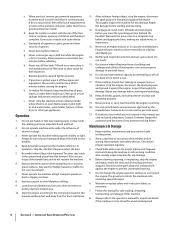
...that may appear on this manual and on the machine before attempting to assemble and operate WARNING- Important Safe Operation Practices ROTATING TINES Do not put hands or feet near rotating parts. Engine exhaust contains carbon monoxide, an odorless and deadly gas. WARNING-... ventilated area. Symbol Description READ THE OPERATOR'S MANUAL(S) Read, understand, and follow the warnings and instructions in this product. ROTATING TINES Do not put hands or feet near rotating parts. Your Responsibility-Restrict the use of this power machine to cool before refueling. ...
...that may appear on this manual and on the machine before attempting to assemble and operate WARNING- Important Safe Operation Practices ROTATING TINES Do not put hands or feet near rotating parts. Engine exhaust contains carbon monoxide, an odorless and deadly gas. WARNING-... ventilated area. Symbol Description READ THE OPERATOR'S MANUAL(S) Read, understand, and follow the warnings and instructions in this product. ROTATING TINES Do not put hands or feet near rotating parts. Your Responsibility-Restrict the use of this power machine to cool before refueling. ...
Operation Manual
Page 8
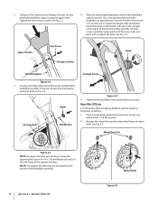
... that will not move, loosen the attaching hex screws (5⁄16-18 x .75) and flange lock nuts (5⁄1618) at approximately waist level when the tines are three height adjustment holes in freewheel, as follows: 1. Tighten the two screws securely. Refer to the outside of the support brackets. Remove the wheel...
... that will not move, loosen the attaching hex screws (5⁄16-18 x .75) and flange lock nuts (5⁄1618) at approximately waist level when the tines are three height adjustment holes in freewheel, as follows: 1. Tighten the two screws securely. Refer to the outside of the support brackets. Remove the wheel...
Operation Manual
Page 10
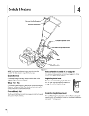
...Figure 4-1 Reverse Handle Assembly (if so equipped) The reverse handle assembly controls the engagement of the reverse drive of the wheels and tines. Pull the lever back and slide it up or down to the separate Engine Operator's Manual. Handlebar Height Adjustment The handlebar height is... settings. TRANSPORT 1" 3" 5" 7" Forward Clutch Bail The forward clutch bail controls the engagement of the forward drive of the wheels and tines. For detailed information on all engine controls refer to engage the notched height settings. Depth Regulator Lever This lever controls the tilling depth of...
...Figure 4-1 Reverse Handle Assembly (if so equipped) The reverse handle assembly controls the engagement of the reverse drive of the wheels and tines. Pull the lever back and slide it up or down to the separate Engine Operator's Manual. Handlebar Height Adjustment The handlebar height is... settings. TRANSPORT 1" 3" 5" 7" Forward Clutch Bail The forward clutch bail controls the engagement of the forward drive of the wheels and tines. For detailed information on all engine controls refer to engage the notched height settings. Depth Regulator Lever This lever controls the tilling depth of...
Operation Manual
Page 11
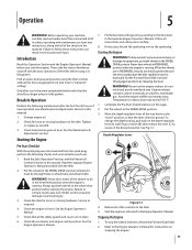
...the lever (C) to follow these instructions can result in these areas may exceed 150° F. 1. See Fig, 5-1. To stop the wheels and tines, release the Forward Clutch Bail. 2. Find an open, level area and practice using it in "transport" setting). See the Maintenance & Adjustments section.... 8. Starting the Engine WARNING! WARNING! Put the wheels in the desired position. Refer to the "travel" position, so that the tines clear the ground. Introduction Read this manual). 1. Check the engine oil level. Check the air cleaner and engine cooling system. Avoid the...
...the lever (C) to follow these instructions can result in these areas may exceed 150° F. 1. See Fig, 5-1. To stop the wheels and tines, release the Forward Clutch Bail. 2. Find an open, level area and practice using it in "transport" setting). See the Maintenance & Adjustments section.... 8. Starting the Engine WARNING! WARNING! Put the wheels in the desired position. Refer to the "travel" position, so that the tines clear the ground. Introduction Read this manual). 1. Check the engine oil level. Check the air cleaner and engine cooling system. Avoid the...
Operation Manual
Page 12
... slowly lower the tines into the soil...tines rotate backward. Don't overload ...tines... the tines are... tine action...tines. Do not push down on the handlebars to try swaying the handlebars from the tines. 1. See Fig. 5-3. 3. Before clearing the tines... the tines to...tines are balanced over the wheels. Follow these procedures to help avoid tangling and to clean the tines... the tines to...Tines The tines have a self-clearing action which digs deeply, uprooting soil and weeds. Engage Drive & Tines 1. For forward motion of the wheels and tines...tines of debris. • If tangling occurs, lift the tines...
... slowly lower the tines into the soil...tines rotate backward. Don't overload ...tines... the tines are... tine action...tines. Do not push down on the handlebars to try swaying the handlebars from the tines. 1. See Fig. 5-3. 3. Before clearing the tines... the tines to...tines are balanced over the wheels. Follow these procedures to help avoid tangling and to clean the tines... the tines to...Tines The tines have a self-clearing action which digs deeply, uprooting soil and weeds. Engage Drive & Tines 1. For forward motion of the wheels and tines...tines of debris. • If tangling occurs, lift the tines...

Operation Manual
Page 13
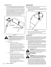
...propel the tiller backward, towards the operator. • When cultivating (breaking up surface soil around plants to destroy weeds, see Fig. 5-4), Adjust the tines to dig only 1" to the surface. • Avoid the temptation to push down on the handlebars in an • When finished in one ... width, followed by successive passes at attempt to force the tiller to dig deeper. If needed, lift up on the handlebars slightly to prevent the tines from digging too deeply. (Cultivating on the rest of the passes. Figure 5-4 Suggested Tilling Patterns 1 2 • When preparing a seedbed, go...
...propel the tiller backward, towards the operator. • When cultivating (breaking up surface soil around plants to destroy weeds, see Fig. 5-4), Adjust the tines to dig only 1" to the surface. • Avoid the temptation to push down on the handlebars in an • When finished in one ... width, followed by successive passes at attempt to force the tiller to dig deeper. If needed, lift up on the handlebars slightly to prevent the tines from digging too deeply. (Cultivating on the rest of the passes. Figure 5-4 Suggested Tilling Patterns 1 2 • When preparing a seedbed, go...
Operation Manual
Page 15
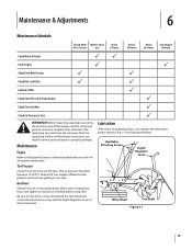
.... Keep both tires. Hardware Check for Wear P Check Air Pressure in Tires P WARNING! Handlebar Attaching Screws Depth Regulator Lever Wheel Shaft Tine Shaft Figure 6-1 15 Maintenance & Adjustments 6 Maintenance Schedule Check After Before each first 2 hours use Every 5 Hours Every 10 Hours Every... P P Check Drive Belt Tension P P Check Nuts and Bolts P P Lubricate Tiller P Check Gear Oil Level in Transmission P Check Tines for loose or missing hardware after every 10 operating hours and tighten or replace (as needed) before using tiller Be sure to check the...
.... Keep both tires. Hardware Check for Wear P Check Air Pressure in Tires P WARNING! Handlebar Attaching Screws Depth Regulator Lever Wheel Shaft Tine Shaft Figure 6-1 15 Maintenance & Adjustments 6 Maintenance Schedule Check After Before each first 2 hours use Every 5 Hours Every 10 Hours Every... P P Check Drive Belt Tension P P Check Nuts and Bolts P P Lubricate Tiller P Check Gear Oil Level in Transmission P Check Tines for loose or missing hardware after every 10 operating hours and tighten or replace (as needed) before using tiller Be sure to check the...
Operation Manual
Page 16
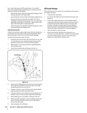
... it reaches the halfway point on level ground, pull the Depth Regulator Lever all the way up the side of the shaft before installing the tines. • Oil the threads on oil can result in an enclosed area where gas fumes could reach an open flame or spark, or where ... Engine Operator's Manual. Transmission Gear Oil Check the transmission gear oil after every 30 hours of the depth regulator lever. • Remove the tines and clean the tine shaft. Clean the tiller and engine. 2. Remove the oil fill plug from gum deposits by removing fuel or by following the storage instructions found...
... it reaches the halfway point on level ground, pull the Depth Regulator Lever all the way up the side of the shaft before installing the tines. • Oil the threads on oil can result in an enclosed area where gas fumes could reach an open flame or spark, or where ... Engine Operator's Manual. Transmission Gear Oil Check the transmission gear oil after every 30 hours of the depth regulator lever. • Remove the tines and clean the tine shaft. Clean the tiller and engine. 2. Remove the oil fill plug from gum deposits by removing fuel or by following the storage instructions found...
Operation Manual
Page 17
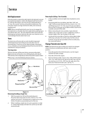
... the belt keeping mechanism built into the belt cover. If removing both tine assemblies, mark them "left side of each tine assembly so that attach a single tine to a tine holder. Before reinstalling the tine assembly, inspect the tine shaft for tine identification and part numbers. Lightly file or sand, as an "over-... 7 Belt Replacement If the drive belt or reverse drive belt needs to be sure to position it so that secure the tine assembly to the tine shaft. A tine assembly consists of grease to do so could damage the belt and/or belt cover. Failure to the shaft. 4. Hex ...
... the belt keeping mechanism built into the belt cover. If removing both tine assemblies, mark them "left side of each tine assembly so that attach a single tine to a tine holder. Before reinstalling the tine assembly, inspect the tine shaft for tine identification and part numbers. Lightly file or sand, as an "over-... 7 Belt Replacement If the drive belt or reverse drive belt needs to be sure to position it so that secure the tine assembly to the tine shaft. A tine assembly consists of grease to do so could damage the belt and/or belt cover. Failure to the shaft. 4. Hex ...
Operation Manual
Page 19
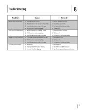
... See "Tilling Tips & Techniques." 3. Internal transmission wear or damage. 1. Review Operation section. 2. Contact local authorized dealer. 4. Replace Tines. 2. Forward Drive Belt slipping. Tighten bolt. 1. See Maintenance & Adjustments Section. 19 Bolt loose in transmission pulley. 3. Improper Depth Regulator ...setting. 3. Troubleshooting 8 Problem Cause Wheels/Tines will not turn Tines turn, but wheels don't Wheels turn, but tines Don't Poor tilling performance 1. Worn, broken, or mis-adjusted drive belt(s). 3. Internal...
... See "Tilling Tips & Techniques." 3. Internal transmission wear or damage. 1. Review Operation section. 2. Contact local authorized dealer. 4. Replace Tines. 2. Forward Drive Belt slipping. Tighten bolt. 1. See Maintenance & Adjustments Section. 19 Bolt loose in transmission pulley. 3. Improper Depth Regulator ...setting. 3. Troubleshooting 8 Problem Cause Wheels/Tines will not turn Tines turn, but wheels don't Wheels turn, but tines Don't Poor tilling performance 1. Worn, broken, or mis-adjusted drive belt(s). 3. Internal...
Operation Manual
Page 20
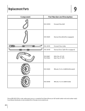
Replacement Parts Component 9 Part Number and Description 954-04090 Forward Drive Belt 954-04091 Reverse Drive Belt (If so equipped) 946-04413 946-04414 Forward Drive Cable Reverse Drive Cable (If so equipped) 742-04227 742-04226 Bolo Tine, 10" (LT) Bolo Tine, 10" (RT) 934-04232 Wheels, 13 x5 x 6 (65M & 655 model) 934-04453 Wheels, 11 x 4-4 (64M model) Phone (800) 828-5500 to order replacement parts or a complete Parts Manual (have your full model number and serial number ready). Parts Manual downloads are also available free of charge at www.troybilt.com. 20
Replacement Parts Component 9 Part Number and Description 954-04090 Forward Drive Belt 954-04091 Reverse Drive Belt (If so equipped) 946-04413 946-04414 Forward Drive Cable Reverse Drive Cable (If so equipped) 742-04227 742-04226 Bolo Tine, 10" (LT) Bolo Tine, 10" (RT) 934-04232 Wheels, 13 x5 x 6 (65M & 655 model) 934-04453 Wheels, 11 x 4-4 (64M model) Phone (800) 828-5500 to order replacement parts or a complete Parts Manual (have your full model number and serial number ready). Parts Manual downloads are also available free of charge at www.troybilt.com. 20
Service Manual
Page 5
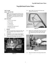
...• 14" tilling width • 10" tine diameter • Adjustable tilling depth up to the Engine Owner's Manual for - Remove the spark plug boot from the spark plug, and ground it to follow along with the Troy-Bilt Factory School. See Figure 2.2. Spark Plug Boot Grounded... Released Figure 2.3 2.4. Spark Plug 2.2. ward clutch spring with Serial Number 1B212G80447. Troy-Bilt Small Frame Tillers Troy-Bilt Small Frame Tillers TUFFY TILLER ABOUT THIS SECTION: NOTE: This section covers the Tuffy rear tine tiller, model 21A-630B063 with the forward clutch bail fully released using a dial ...
...• 14" tilling width • 10" tine diameter • Adjustable tilling depth up to the Engine Owner's Manual for - Remove the spark plug boot from the spark plug, and ground it to follow along with the Troy-Bilt Factory School. See Figure 2.2. Spark Plug Boot Grounded... Released Figure 2.3 2.4. Spark Plug 2.2. ward clutch spring with Serial Number 1B212G80447. Troy-Bilt Small Frame Tillers Troy-Bilt Small Frame Tillers TUFFY TILLER ABOUT THIS SECTION: NOTE: This section covers the Tuffy rear tine tiller, model 21A-630B063 with the forward clutch bail fully released using a dial ...
Service Manual
Page 11
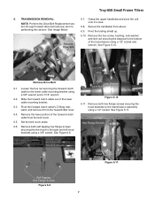
... handlebar from the forward idler lever. 6.4. Pivot the trailing shield up. Remove Drive Belt 6.1. See Figure 6.6. Remove both self tapping hex flange screws securing the tine hood to the transmission assembly using a 3/8" socket. See Image Below 6.9. Lock Washer Lock Nut Hex Screw Figure 6.10 6.11. tion through forward drive belt ... upper handlebar and pivot the unit NOTE: Perform the Drive Belt Replacement sec- Slide the forward clutch cable out of the lower cable mounting bracket. 6.3. Troy-Bilt Small Frame Tillers 6. performing this section. See Figure 6.10.
... handlebar from the forward idler lever. 6.4. Pivot the trailing shield up. Remove Drive Belt 6.1. See Figure 6.6. Remove both self tapping hex flange screws securing the tine hood to the transmission assembly using a 3/8" socket. See Image Below 6.9. Lock Washer Lock Nut Hex Screw Figure 6.10 6.11. tion through forward drive belt ... upper handlebar and pivot the unit NOTE: Perform the Drive Belt Replacement sec- Slide the forward clutch cable out of the lower cable mounting bracket. 6.3. Troy-Bilt Small Frame Tillers 6. performing this section. See Figure 6.10.
Service Manual
Page 12
... Raise the Unit Up Figure 6.14 6.15. See Figure 6.15. Lower the unit back onto the tines. Hood Brackets Drag Bar Figure 6.12 NOTE: There is resting on the tines and not on the trailing shield. Troy-Bilt Small Frame Tillers 6.12. Depth Regulator Assembly 6.14. Cut A Way for Spiral Pin 6.13. Remove both...
... Raise the Unit Up Figure 6.14 6.15. See Figure 6.15. Lower the unit back onto the tines. Hood Brackets Drag Bar Figure 6.12 NOTE: There is resting on the tines and not on the trailing shield. Troy-Bilt Small Frame Tillers 6.12. Depth Regulator Assembly 6.14. Cut A Way for Spiral Pin 6.13. Remove both...
Service Manual
Page 15
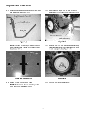
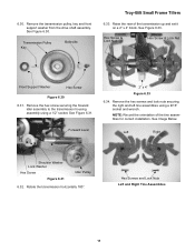
... Lever 2" x 4" Figure 6.33 6.34. Rotate the transmission horizontally 180°. Hex Screws and Lock Nuts Left and Right Tine Assemblies 11 6.30. Transmission Pulley Key Belleville Troy-Bilt Small Frame Tillers 6.33. Raise the rear of the tine assemblies for correct installation. Remove the hex screws and lock nuts securing the right and left...
... Lever 2" x 4" Figure 6.33 6.34. Rotate the transmission horizontally 180°. Hex Screws and Lock Nuts Left and Right Tine Assemblies 11 6.30. Transmission Pulley Key Belleville Troy-Bilt Small Frame Tillers 6.33. Raise the rear of the tine assemblies for correct installation. Remove the hex screws and lock nuts securing the right and left...
Service Manual
Page 16
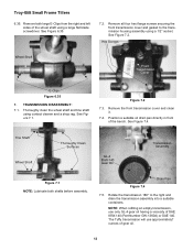
...assembly using a 1/2" socket. Remove the front transmission cover and clean it. 7.4. Drain Pan Figure 7.4 7.5. TRANSMISSION DISASSEMBLY: 7.1. Tine Shaft Wheel Shaft Thoroughly Clean Surfaces GL-4 85W-140 Gear Oil Transmission Assembly Figure 7.1 NOTE: Lubricate both large E-Clips from ... of the bench. See Figure 7.2. Hex Screws Wheel Shaft Front Transmission Cover E-Clips Figure 6.35 7. Troy-Bilt Small Frame Tillers 6.35. Thoroughly clean the wheel shaft and tine shaft using a large flat blade screwdriver. Figure 7.2 7.3. Remove both shafts before assembly. See Figure ...
...assembly using a 1/2" socket. Remove the front transmission cover and clean it. 7.4. Drain Pan Figure 7.4 7.5. TRANSMISSION DISASSEMBLY: 7.1. Tine Shaft Wheel Shaft Thoroughly Clean Surfaces GL-4 85W-140 Gear Oil Transmission Assembly Figure 7.1 NOTE: Lubricate both large E-Clips from ... of the bench. See Figure 7.2. Hex Screws Wheel Shaft Front Transmission Cover E-Clips Figure 6.35 7. Troy-Bilt Small Frame Tillers 6.35. Thoroughly clean the wheel shaft and tine shaft using a large flat blade screwdriver. Figure 7.2 7.3. Remove both shafts before assembly. See Figure ...
Service Manual
Page 17
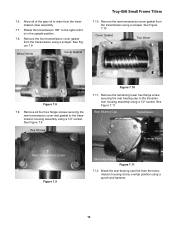
... See Figure 7.11. Rotate the transmission 180° to the transmission housing assembly using a 1/2" socket. Wheel Worm Cover Gasket Troy-Bilt Small Frame Tillers 7.10. Remove all of the gear oil to the transmission housing assembly using a 1/2" socket. Hex Screws Figure ...transmission cover gasket from the transmission using a scraper. Remove the rear transmission cover gasket from the transmission using a scraper. Cover Gasket Tine Worm Figure 7.8 7.9. Break the rear bearing cap free from the transmission case assembly. 7.7. Allow all four hex flange screws securing ...
... See Figure 7.11. Rotate the transmission 180° to the transmission housing assembly using a 1/2" socket. Wheel Worm Cover Gasket Troy-Bilt Small Frame Tillers 7.10. Remove all of the gear oil to the transmission housing assembly using a 1/2" socket. Hex Screws Figure ...transmission cover gasket from the transmission using a scraper. Remove the rear transmission cover gasket from the transmission using a scraper. Cover Gasket Tine Worm Figure 7.8 7.9. Break the rear bearing cap free from the transmission case assembly. 7.7. Allow all four hex flange screws securing ...
Service Manual
Page 23
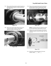
... oil seals from the right and left hand sides of the tine shaft using an oil seal removal tool. Measure the overall thicknesses of the shim washers, Right _____, Left _____. 19 Oil Seal Troy-Bilt Small Frame Tillers 7.49. External Shims Figure 7.49 NOTE: Two paper clips with a small 90...° bend at the end works well for external shim removal. 7.50. See Figure 7.47. Tine Shaft Tine Shaft Figure 7.47 7.48. Retaining Ring Dial Caliper...
... oil seals from the right and left hand sides of the tine shaft using an oil seal removal tool. Measure the overall thicknesses of the shim washers, Right _____, Left _____. 19 Oil Seal Troy-Bilt Small Frame Tillers 7.49. External Shims Figure 7.49 NOTE: Two paper clips with a small 90...° bend at the end works well for external shim removal. 7.50. See Figure 7.47. Tine Shaft Tine Shaft Figure 7.47 7.48. Retaining Ring Dial Caliper...


