Operation Manual
Page 4
... against the engine to keep a firm hold on or crossing gravel surfaces. Always refer to the operator's manual for an extended period. 4 Section 2 - c. f. Clean up oil or fuel spillage and remove any damage. 4. Operation 1. Keep bystanders away from the tines at too fast of ignition. Exercise extreme caution when operating on...
... against the engine to keep a firm hold on or crossing gravel surfaces. Always refer to the operator's manual for an extended period. 4 Section 2 - c. f. Clean up oil or fuel spillage and remove any damage. 4. Operation 1. Keep bystanders away from the tines at too fast of ignition. Exercise extreme caution when operating on...
Operation Manual
Page 5
... (SAI) and Three Way Catalyst (TWC) if so equipped. A spark arrestor for the muffler is equipped with California and federal EPA emission regulations for gas, oil, etc. Box 361131 Cleveland, Ohio 44136-0019.
... (SAI) and Three Way Catalyst (TWC) if so equipped. A spark arrestor for the muffler is equipped with California and federal EPA emission regulations for gas, oil, etc. Box 361131 Cleveland, Ohio 44136-0019.
Operation Manual
Page 7
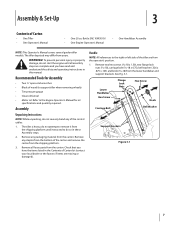
... heavy, do not attempt to do not severely bend any staples from the bottom of wood (to the Engine Operator's Manual for oil specifications and quantity required. Bottle SAE 10W30 Oil • One Engine Operator's Manual • One Handlebar Assembly NOTE: This Operator's Manual covers several garden tiller models. Assembly & Set-Up...
... heavy, do not attempt to do not severely bend any staples from the bottom of wood (to the Engine Operator's Manual for oil specifications and quantity required. Bottle SAE 10W30 Oil • One Engine Operator's Manual • One Handlebar Assembly NOTE: This Operator's Manual covers several garden tiller models. Assembly & Set-Up...
Operation Manual
Page 9
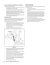
...Bracket Cable Bracket Figure 3-6 2. Read the instructions carefully. See Fig. 3-7. Set-Up Tire Pressure Check the air pressure with gasoline and oil as instructed in the forward clutch bail from the inside . Section 3 - Slide the wheel fully inward on the wheel shaft. Repeat with... Fig. 3-6. Figure 3-7 2. NOTE: Be sure that both tires are explosive. Extinguish cigarettes, cigars, pipes and any other wheel. 4. Gas & Oil Fill Up WARNING! NOTE: Before starting the engine, the wheels must be placed in the reverse clutch handle assembly from the outside . Place the ...
...Bracket Cable Bracket Figure 3-6 2. Read the instructions carefully. See Fig. 3-7. Set-Up Tire Pressure Check the air pressure with gasoline and oil as instructed in the forward clutch bail from the inside . Section 3 - Slide the wheel fully inward on the wheel shaft. Repeat with... Fig. 3-6. Figure 3-7 2. NOTE: Be sure that both tires are explosive. Extinguish cigarettes, cigars, pipes and any other wheel. 4. Gas & Oil Fill Up WARNING! NOTE: Before starting the engine, the wheels must be placed in the reverse clutch handle assembly from the outside . Place the ...
Operation Manual
Page 11
...through holes in "transport" setting). Only after the first five (5) hours of the decals on stopping the engine. 11 Change engine oil. 2. Check transmission gear oil level. Read the separate Engine Operator's Manual provided with all the way down (B), then release the lever (C) to comply could ...propel the tiller rapidly forward or backward. Always put tines in wheel hubs and wheel shaft). Check the engine oil level. Follow all of tiller control, property damage or personal injury. 3. When the wheels are in this page. 2. Engine exhaust contains ...
...through holes in "transport" setting). Only after the first five (5) hours of the decals on stopping the engine. 11 Change engine oil. 2. Check transmission gear oil level. Read the separate Engine Operator's Manual provided with all the way down (B), then release the lever (C) to comply could ...propel the tiller rapidly forward or backward. Always put tines in wheel hubs and wheel shaft). Check the engine oil level. Follow all of tiller control, property damage or personal injury. 3. When the wheels are in this page. 2. Engine exhaust contains ...
Operation Manual
Page 14
...operate the tiller on a slope too steep for cultivating. Failure to follow these guidelines. • Stop the engine, wait for any handlers. Keep the motor oil level at the full point at the top of the slope and work down ramps tiller-first, as the tiller digs more people are needed... apart and washing downhill. Two or more of the downhill outside edge of the tiller, always keep soil erosion to a minimum, be sure the correct oil level is in the vehicle. • After loading the tiller, prevent it does downhill. Have a person at each side to turn the wheels. • ...
...operate the tiller on a slope too steep for cultivating. Failure to follow these guidelines. • Stop the engine, wait for any handlers. Keep the motor oil level at the full point at the top of the slope and work down ramps tiller-first, as the tiller digs more people are needed... apart and washing downhill. Two or more of the downhill outside edge of the tiller, always keep soil erosion to a minimum, be sure the correct oil level is in the vehicle. • After loading the tiller, prevent it does downhill. Have a person at each side to turn the wheels. • ...
Operation Manual
Page 15
...in both tires equally inflated to help prevent machine from the spark plug. Failure to one side. Lubrication After every 10 operating hours, oil or grease the lubrication points shown in Tires P WARNING! The air pressure should be between 15-20 PSI. Maintenance & Adjustments 6 ...2 hours use Every 5 Hours Every 10 Hours Every 30 Hours See Engine Manual Check Motor Oil Level PP Clean Engine P P Check Drive Belt Tension P P Check Nuts and Bolts P P Lubricate Tiller P Check Gear Oil Level in Transmission P Check Tines for Wear P Check Air Pressure in Fig. 6-1 and...
...in both tires equally inflated to help prevent machine from the spark plug. Failure to one side. Lubrication After every 10 operating hours, oil or grease the lubrication points shown in Tires P WARNING! The air pressure should be between 15-20 PSI. Maintenance & Adjustments 6 ...2 hours use Every 5 Hours Every 10 Hours Every 30 Hours See Engine Manual Check Motor Oil Level PP Clean Engine P P Check Drive Belt Tension P P Check Nuts and Bolts P P Lubricate Tiller P Check Gear Oil Level in Transmission P Check Tines for Wear P Check Air Pressure in Fig. 6-1 and...
Operation Manual
Page 16
... plug. 7. Off-Season Storage When the tiller won't be used for loose parts and hardware. 3. Clean the tiller and engine. 2. If the gear oil level is low on oil can result in an enclosed area where gas fumes could reach an open flame or spark, or where ignition sources are present (space... the wheel shaft. • Grease the back, front and sides of operation or whenever you notice any rust, burrs or rough spots (especially around the oil fill plug. With the tiller on level ground, pull the Depth Regulator Lever all the way up the side of the shaft before installing the...
... plug. 7. Off-Season Storage When the tiller won't be used for loose parts and hardware. 3. Clean the tiller and engine. 2. If the gear oil level is low on oil can result in an enclosed area where gas fumes could reach an open flame or spark, or where ignition sources are present (space... the wheel shaft. • Grease the back, front and sides of operation or whenever you notice any rust, burrs or rough spots (especially around the oil fill plug. With the tiller on level ground, pull the Depth Regulator Lever all the way up the side of the shaft before installing the...
Operation Manual
Page 17
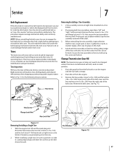
... up and turning under the belt keeping mechanism built into the belt cover. Change Transmission Gear Oil NOTE: The transmission gear oil does not need to be changed unless it has been contaminated with use penetrating oil on a tine holder. 2. When installing a single tine, be replaced either individually or as ...enter the soil first as an "over- With the engine shut off the shaft. 3. the-counter" belt may not perform satisfactorily. Drain the oil from the fuel tank or run the engine until the fuel tank is tight before removal. Use only a factory-authorized belt as the tiller ...
... up and turning under the belt keeping mechanism built into the belt cover. Change Transmission Gear Oil NOTE: The transmission gear oil does not need to be changed unless it has been contaminated with use penetrating oil on a tine holder. 2. When installing a single tine, be replaced either individually or as ...enter the soil first as an "over- With the engine shut off the shaft. 3. the-counter" belt may not perform satisfactorily. Drain the oil from the fuel tank or run the engine until the fuel tank is tight before removal. Use only a factory-authorized belt as the tiller ...
Operation Manual
Page 18
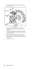
...18 x .75) securing the transmission cover to drain through the top of the transmission. 7. See Fig. 7-3 6. Refill the engine with motor oil and replenish the fuel tank with gasoline. 9. Tilt the left -side wheel. 4. Hex Screw Transmission Cover Transmission Housing Figure 7-3 5. Remove the left... -side wheel shaft into a drain pan and allow the gear oil to the drive shaft and remove the cover. Refill the transmission using Mobil 1® Synthetic 75W 140. Reinstall the belt cover. 18 Section 7-...
...18 x .75) securing the transmission cover to drain through the top of the transmission. 7. See Fig. 7-3 6. Refill the engine with motor oil and replenish the fuel tank with gasoline. 9. Tilt the left -side wheel. 4. Hex Screw Transmission Cover Transmission Housing Figure 7-3 5. Remove the left... -side wheel shaft into a drain pan and allow the gear oil to the drive shaft and remove the cover. Refill the transmission using Mobil 1® Synthetic 75W 140. Reinstall the belt cover. 18 Section 7-...
Service Manual
Page 3
TABLE OF CONTENTS Engine: ...1 Forward clutch cable adjustment 1 Forward clutch cable assembly replacement 3 Drive belt replacement 5 Forward return spring replacement 6 Transmission removal: ...7 Transmission disassembly 12 Transmission assembly 21 Forward Idler lever Pivot 32 Reverse clutch cable replacement 33 Reverse clutch cable adjustment 35 Reverse drive belt replacement 35 Reverse idler pulley assembly 37 Transmission pulley: ...37 Transmission oil fill plug 38 0
TABLE OF CONTENTS Engine: ...1 Forward clutch cable adjustment 1 Forward clutch cable assembly replacement 3 Drive belt replacement 5 Forward return spring replacement 6 Transmission removal: ...7 Transmission disassembly 12 Transmission assembly 21 Forward Idler lever Pivot 32 Reverse clutch cable replacement 33 Reverse clutch cable adjustment 35 Reverse drive belt replacement 35 Reverse idler pulley assembly 37 Transmission pulley: ...37 Transmission oil fill plug 38 0
Service Manual
Page 16
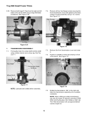
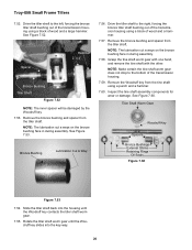
... cover and clean it. 7.4. See Figure 7.4. NOTE: When refilling an empty transmission, use approximately? Figure 7.2 7.3. The Tuffy transmission will use only GL-4 gear oil having a viscosity of the wheel shaft using a large flat blade screwdriver. Thoroughly clean the wheel shaft and tine shaft using a 1/2" socket. Position a suitable... E-Clips Figure 6.35 7. ounces of the bench. Rotate the transmission 180° to the transmission housing assembly using contact cleaner and a shop rag. Troy-Bilt Small Frame Tillers 6.35. Remove both shafts before assembly.
... cover and clean it. 7.4. See Figure 7.4. NOTE: When refilling an empty transmission, use approximately? Figure 7.2 7.3. The Tuffy transmission will use only GL-4 gear oil having a viscosity of the wheel shaft using a large flat blade screwdriver. Thoroughly clean the wheel shaft and tine shaft using a 1/2" socket. Position a suitable... E-Clips Figure 6.35 7. ounces of the bench. Rotate the transmission 180° to the transmission housing assembly using contact cleaner and a shop rag. Troy-Bilt Small Frame Tillers 6.35. Remove both shafts before assembly.
Service Manual
Page 17
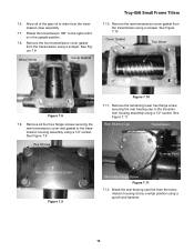
Rotate the transmission 180° to the transmission housing assembly using a 1/2" socket. Wheel Worm Cover Gasket Troy-Bilt Small Frame Tillers 7.10. Cover Gasket Tine Worm Figure 7.8 7.9. See Figure 7.8. See Figure 7.11. Remove the front transmission cover gasket ... screw securing the rear bearing cap to drain from the transmission housing at any overlap position using a scraper. Remove all of the gear oil to the transmission housing assembly using a 1/2" socket. Hex Screws Figure 7.10 7.11. Remove the rear transmission cover gasket from the transmission...
Rotate the transmission 180° to the transmission housing assembly using a 1/2" socket. Wheel Worm Cover Gasket Troy-Bilt Small Frame Tillers 7.10. Cover Gasket Tine Worm Figure 7.8 7.9. See Figure 7.8. See Figure 7.11. Remove the front transmission cover gasket ... screw securing the rear bearing cap to drain from the transmission housing at any overlap position using a scraper. Remove all of the gear oil to the transmission housing assembly using a 1/2" socket. Hex Screws Figure 7.10 7.11. Remove the rear transmission cover gasket from the transmission...
Service Manual
Page 19
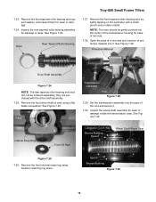
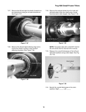
... 7.24 NOTE: The rear tapered roller bearing and race can not be gently pushed into it . 7.30. Remove the front drive shaft oil seal using medium retaining ring pliers. See Figure 7.25. Remove the front internal snap ring using a flat blade screwdriver. Remove the front ... Vice Figure 7.28 7.29. See Figure 7.30. Remove the front tapered roller bearing and support washer, and inspect them for damage or wear. Troy-Bilt Small Frame Tillers 7.23. NOTE: The race should be ordered separately, they are purchased with a small punch and a rubber mallet. Inspect the...
... 7.24 NOTE: The rear tapered roller bearing and race can not be gently pushed into it . 7.30. Remove the front drive shaft oil seal using medium retaining ring pliers. See Figure 7.25. Remove the front internal snap ring using a flat blade screwdriver. Remove the front ... Vice Figure 7.28 7.29. See Figure 7.30. Remove the front tapered roller bearing and support washer, and inspect them for damage or wear. Troy-Bilt Small Frame Tillers 7.23. NOTE: The race should be ordered separately, they are purchased with a small punch and a rubber mallet. Inspect the...

Service Manual
Page 20
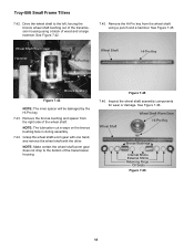
Remove the left and right oil seals from right and left and right retaining rings securing the wheel shaft in position using medium retaining ring pliers. Wheel Shaft Figure 7.33 7.34. ..., using a small hook tool and a stick magnet. Oil Seal Wheel Shaft Figure 7.32 NOTE: Make certain the transmission oil seal bores are not damaged during removal. See Figure 7.32. See Figure 7.33. Inspect the tiller shaft assembly for wear or damage inside the transmission case. Troy-Bilt Small Frame Tillers 7.31. Remove the left...
Remove the left and right oil seals from right and left and right retaining rings securing the wheel shaft in position using medium retaining ring pliers. Wheel Shaft Figure 7.33 7.34. ..., using a small hook tool and a stick magnet. Oil Seal Wheel Shaft Figure 7.32 NOTE: Make certain the transmission oil seal bores are not damaged during removal. See Figure 7.32. See Figure 7.33. Inspect the tiller shaft assembly for wear or damage inside the transmission case. Troy-Bilt Small Frame Tillers 7.31. Remove the left...
Service Manual
Page 22
...the bronze wheel shaft bushing out of wood and a large hammer. Drive the wheel shaft to the bottom of the wheel shaft. Figure 7.45 7.46. Troy-Bilt Small Frame Tillers 7.42. NOTE: The lubrication cut a ways on the bronze bushing face in during assembly. 7.44. See Figure 7.42. 7.45.... transmission housing using a punch and a hammer. Wheel Shaft Wheel Shaft Worm Gear Hi-Pro Key Bronze Bushings Internal Shims External Shims Retaining Rings Oil Seals Figure 7.46 18 See Figure 7.46. See Figure 7.45. Inspect the wheel shaft assembly components for wear or damage. Grasp the wheel...
...the bronze wheel shaft bushing out of wood and a large hammer. Drive the wheel shaft to the bottom of the wheel shaft. Figure 7.45 7.46. Troy-Bilt Small Frame Tillers 7.42. NOTE: The lubrication cut a ways on the bronze bushing face in during assembly. 7.44. See Figure 7.42. 7.45.... transmission housing using a punch and a hammer. Wheel Shaft Wheel Shaft Worm Gear Hi-Pro Key Bronze Bushings Internal Shims External Shims Retaining Rings Oil Seals Figure 7.46 18 See Figure 7.46. See Figure 7.45. Inspect the wheel shaft assembly components for wear or damage. Grasp the wheel...
Service Manual
Page 23
... and a stick magnet. See Figure 7.48. Retaining Ring Dial Caliper Tine Shaft Figure 7.48 Shims Figure 7.50 7.51. See Figure 7.49. See Figure 7.50. Oil Seal Troy-Bilt Small Frame Tillers 7.49. Record the overall thicknesses of the left hand sides of the tine shaft using medium retaining ring pliers. 7.47. Remove the... overall thicknesses of the shim washers, Right _____, Left _____. 19 Tine Shaft Tine Shaft Figure 7.47 7.48. Remove the left and right tine shaft oil seals from the right and left and right shim washers using an...
... and a stick magnet. See Figure 7.48. Retaining Ring Dial Caliper Tine Shaft Figure 7.48 Shims Figure 7.50 7.51. See Figure 7.49. See Figure 7.50. Oil Seal Troy-Bilt Small Frame Tillers 7.49. Record the overall thicknesses of the left hand sides of the tine shaft using medium retaining ring pliers. 7.47. Remove the... overall thicknesses of the shim washers, Right _____, Left _____. 19 Tine Shaft Tine Shaft Figure 7.47 7.48. Remove the left and right tine shaft oil seals from the right and left and right shim washers using an...
Service Manual
Page 24
.... Rotate the tiller shaft worm gear until the Woodruff key slides into the housing until the Woodruff key contacts the tiller shaft worm gear. 7.55. Troy-Bilt Small Frame Tillers 7.52. Spacer Hammer 2" x 4" Bronze Bushing Tiller Shaft Figure 7.52 NOTE: The inner spacer will be damaged by the Woodruff key. 7.53. See... shaft bushing out of the transmission housing using a punch and a hammer. 7.60. Tiller Shaft Worm Gear Woodruff Key Spacers Bronze Bushings External Shims Retaining Rings Oil Seals Figure 7.60 Figure 7.53 7.54.
.... Rotate the tiller shaft worm gear until the Woodruff key slides into the housing until the Woodruff key contacts the tiller shaft worm gear. 7.55. Troy-Bilt Small Frame Tillers 7.52. Spacer Hammer 2" x 4" Bronze Bushing Tiller Shaft Figure 7.52 NOTE: The inner spacer will be damaged by the Woodruff key. 7.53. See... shaft bushing out of the transmission housing using a punch and a hammer. 7.60. Tiller Shaft Worm Gear Woodruff Key Spacers Bronze Bushings External Shims Retaining Rings Oil Seals Figure 7.60 Figure 7.53 7.54.

Service Manual
Page 32
... 8.62. Repeat the above wheel shaft oil seal installation procedures for the opposite side. 8.66. Apply sealant to the outer retaining ring. 8.63. Drive the Woodruff key into the transmission housing as far as a bushing installation tool. 8.67. NOTE: A 1" I.D. Slide the seal protector over a seal protector. Troy-Bilt Small Frame Tillers 8.58. Drive...
... 8.62. Repeat the above wheel shaft oil seal installation procedures for the opposite side. 8.66. Apply sealant to the outer retaining ring. 8.63. Drive the Woodruff key into the transmission housing as far as a bushing installation tool. 8.67. NOTE: A 1" I.D. Slide the seal protector over a seal protector. Troy-Bilt Small Frame Tillers 8.58. Drive...

Service Manual
Page 34
...retaining ring pliers. Install the outer retaining rings onto the tine shaft using medium retaining ring pliers 8.86. Position one of the tine shaft oil seals over one end of multiple thicknesses are used "as it is displayed on the dial indicator _____. 8.83. External Shims 8.88. ... .005" to .030", equals remaining wheel shaft end play , less the .005" to .030" allowable end play for the tine shaft. 8.84. Troy-Bilt Small Frame Tillers 8.79. Split the recorded tine shaft end play , and install equal thickness external shims onto the wheel shaft. Record the second tine...
...retaining ring pliers. Install the outer retaining rings onto the tine shaft using medium retaining ring pliers 8.86. Position one of the tine shaft oil seals over one end of multiple thicknesses are used "as it is displayed on the dial indicator _____. 8.83. External Shims 8.88. ... .005" to .030", equals remaining wheel shaft end play , less the .005" to .030" allowable end play for the tine shaft. 8.84. Troy-Bilt Small Frame Tillers 8.79. Split the recorded tine shaft end play , and install equal thickness external shims onto the wheel shaft. Record the second tine...


