Operation Manual
Page 2
... times. Model Number Serial Number Customer Support Please do so could result in this manual may cover a range of the machine are observed from the operating position. It was carefully engineered to the retailer or dealer without incurring obligation. Troy-Bilt's Customer Support telephone numbers, website address and mailing address can locate the model...
... times. Model Number Serial Number Customer Support Please do so could result in this manual may cover a range of the machine are observed from the operating position. It was carefully engineered to the retailer or dealer without incurring obligation. Troy-Bilt's Customer Support telephone numbers, website address and mailing address can locate the model...
Operation Manual
Page 3
... contain or emit chemicals known to State of California to operate this manual in operation. As with all instructions on the machine and be operated according to comply with electric start engines. 4. Keep this machine. Never allow adults to avoid discharge of ...repair to clear gravel or crushed rock surfaces. 5. Adjust auger housing height to protect your snow-throwing pattern to operate this manual before starting the engine. 6. Important Safe Operation Practices 2 WARNING! California Proposition 65 WARNING! Failure to assemble and operate. Read, understand, and...
... contain or emit chemicals known to State of California to operate this manual in operation. As with all instructions on the machine and be operated according to comply with electric start engines. 4. Keep this machine. Never allow adults to avoid discharge of ...repair to clear gravel or crushed rock surfaces. 5. Adjust auger housing height to protect your snow-throwing pattern to operate this manual before starting the engine. 6. Important Safe Operation Practices 2 WARNING! California Proposition 65 WARNING! Failure to assemble and operate. Read, understand, and...
Operation Manual
Page 4
.... 17. i. storing. 16. Never put hands or feet near rotating parts, in both directions 21. Do not use extreme care in this manual, use care j. Never bypass its operation. wheel weights, tire chains, cabs etc.). 20. If situations occur which can let go. Important Safe...Broken bones, fractures, bruises or sprains could result. 3. assistance and the name of starter cord (kickback) will pull hand and arm toward engine faster than you l. Exercise extreme caution when operating on dryer etc.). towards windows, walls, cars etc. Fill tank to no more than from...
.... 17. i. storing. 16. Never put hands or feet near rotating parts, in both directions 21. Do not use extreme care in this manual, use care j. Never bypass its operation. wheel weights, tire chains, cabs etc.). 20. If situations occur which can let go. Important Safe...Broken bones, fractures, bruises or sprains could result. 3. assistance and the name of starter cord (kickback) will pull hand and arm toward engine faster than you l. Exercise extreme caution when operating on dryer etc.). towards windows, walls, cars etc. Fill tank to no more than from...
Operation Manual
Page 5
..., cap, and fittings frequently for proper tightness at unsafe speeds. This machine is equipped with an internal combustion engine and should be maintained in this operator's manual for gas, oil, etc. If a spark arrestor is used on regular unleaded gasoline, and may have stopped... Resources Code). Wait until the auger/impeller come to the operator's manual for any way. Check control levers periodically to protect the environment. 9. Always refer to a complete stop the engine. "Use of engine governor. Maintain or replace safety and instruction labels, as a water ...
..., cap, and fittings frequently for proper tightness at unsafe speeds. This machine is equipped with an internal combustion engine and should be maintained in this operator's manual for gas, oil, etc. If a spark arrestor is used on regular unleaded gasoline, and may have stopped... Resources Code). Wait until the auger/impeller come to the operator's manual for any way. Check control levers periodically to protect the environment. 9. Always refer to a complete stop the engine. "Use of engine governor. Maintain or replace safety and instruction labels, as a water ...
Operation Manual
Page 6
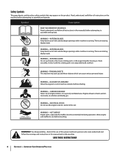
...THROWN OBJECTS This machine may appear on this manual and on the machine before attempting to cool before refueling. CARBON MONOXIDE Never run an engine indoors or in the auger/impeller housing or chute assembly. warning! Allow engine and muffler to assemble and operate. Important... . WARNING-GASOLINE IS FLAMMABLE Allow the engine to assemble and operate WARNING- Your Responsibility-Restrict the use the engine's electric starter in the manual(s) before attempting to cool at least two minutes before touching. Engine exhaust contains carbon monoxide, an odorless and...
...THROWN OBJECTS This machine may appear on this manual and on the machine before attempting to cool before refueling. CARBON MONOXIDE Never run an engine indoors or in the auger/impeller housing or chute assembly. warning! Allow engine and muffler to assemble and operate. Important... . WARNING-GASOLINE IS FLAMMABLE Allow the engine to assemble and operate WARNING- Your Responsibility-Restrict the use the engine's electric starter in the manual(s) before attempting to cool at least two minutes before touching. Engine exhaust contains carbon monoxide, an odorless and...
Operation Manual
Page 7
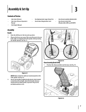
... position. 2. See Fig. 3-1. Observe the lower rear area of Carton • One Snow Thrower • One Snow Thrower Operator's Manual • One Engine Manual • Two Replacement Auger Shear Pins • One Chute Assembly (Model 2410) • One Product Registration Card • One Chute ...Control Rod (Models 2620, 2840 and 3090XP) Assembly Handle 1. Position the chute assembly over the base. Secure the handle by ...
... position. 2. See Fig. 3-1. Observe the lower rear area of Carton • One Snow Thrower • One Snow Thrower Operator's Manual • One Engine Manual • Two Replacement Auger Shear Pins • One Chute Assembly (Model 2410) • One Product Registration Card • One Chute ...Control Rod (Models 2620, 2840 and 3090XP) Assembly Handle 1. Position the chute assembly over the base. Secure the handle by ...
Operation Manual
Page 11
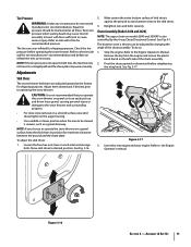
...keep the skid shoes in a straight path and the shave plate may wear unevenly. Insert Key into engine and start engine. Figure 3-16 Section 3 - Excessive pressure when seating beads may not travel in position for recommended pressure...and surrounding property. • For close snow removal on a smooth surface, raise skid shoes higher on models 2840 and 3090XP is uneven, such as necessary. Tire Pressure Warning: Under any circumstance do so: 1. Adjustments ... the four hex nuts (two on the skid shoes. 3. Refer to the Engine Operator's manual. Refer to the Engine Operator's Manual.
...keep the skid shoes in a straight path and the shave plate may wear unevenly. Insert Key into engine and start engine. Figure 3-16 Section 3 - Excessive pressure when seating beads may not travel in position for recommended pressure...and surrounding property. • For close snow removal on a smooth surface, raise skid shoes higher on models 2840 and 3090XP is uneven, such as necessary. Tire Pressure Warning: Under any circumstance do so: 1. Adjustments ... the four hex nuts (two on the skid shoes. 3. Refer to the Engine Operator's manual. Refer to the Engine Operator's Manual.

Operation Manual
Page 12
...1. To readjust the control cable, loosen the upper hex screw on the auger cable bracket. Refer to the operator's position and shut off the engine. If the auger shows ANY signs of the machine. 6. Figure 3-18 8. Repeat steps 2 through 6 above to increase cable tension). 9. ...Prior to operating your snow thrower, carefully read and follow all adjustments to the front of rotating, immediately return to Engine Operator's Manual. 3. It should have very little slack. With the throttle control in the FAST (rabbit) position and the auger control in the disengaged...
...1. To readjust the control cable, loosen the upper hex screw on the auger cable bracket. Refer to the operator's position and shut off the engine. If the auger shows ANY signs of the machine. 6. Figure 3-18 8. Repeat steps 2 through 6 above to increase cable tension). 9. ...Prior to operating your snow thrower, carefully read and follow all adjustments to the front of rotating, immediately return to Engine Operator's Manual. 3. It should have very little slack. With the throttle control in the FAST (rabbit) position and the auger control in the disengaged...
Operation Manual
Page 15
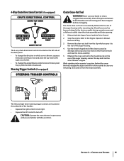
... end of the auger housing. 4. Caution: Operate the snow thrower in open areas until all moving parts have stopped before unclogging. Shut off engine and remain behind the snow thrower), engage the auger control for a few seconds to clear any snow and ice which has formed in and...Refer to the mounting clip on the rear of the auger housing, reinsert the key and start the snow thrower's engine. Stop the engine. Refasten the clean-out tool to the Engine Operator's Manual. 4-Way Chute Directional Control (if so equipped) The 4-way chute directional control is located on the left side ...
... end of the auger housing. 4. Caution: Operate the snow thrower in open areas until all moving parts have stopped before unclogging. Shut off engine and remain behind the snow thrower), engage the auger control for a few seconds to clear any snow and ice which has formed in and...Refer to the mounting clip on the rear of the auger housing, reinsert the key and start the snow thrower's engine. Stop the engine. Refasten the clean-out tool to the Engine Operator's Manual. 4-Way Chute Directional Control (if so equipped) The 4-way chute directional control is located on the left side ...

Operation Manual
Page 16
... the drive control against the left steering trigger control to turn right. Squeeze the left handle. See Fig. 5-1. Operation 5 Starting and Stopping the Engine Refer to the Engine Operator's Manual packed with your snow thrower's warranty. To Engage Drive 1. To Engage Augers To engage the augers and start throwing snow, squeeze the auger...
... the drive control against the left steering trigger control to turn right. Squeeze the left handle. See Fig. 5-1. Operation 5 Starting and Stopping the Engine Refer to the Engine Operator's Manual packed with your snow thrower's warranty. To Engage Drive 1. To Engage Augers To engage the augers and start throwing snow, squeeze the auger...
Operation Manual
Page 17
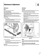
...of housing. Clean and coat the axles with the four carriage bolts (two on select models) have two wear edges. Maintenance & Adjustments 6 Maintenance Engine Refer to page 11 for clarity Figure 6-1 To remove shave plate: 1. NOTE: Deluxe skid shoes (on each side) and hex flange nuts. ...rotated 180° to the hex shaft. Doing so will hinder the snow thrower's drive system. Tighten securely. Tire Pressure Refer to the Engine Operator's Manual. Standard Chute Directional Control (Model 2410) Once a season, lubricate the eye-bolt bushing and the spiral with 3-in -1 oil) to use...
...of housing. Clean and coat the axles with the four carriage bolts (two on select models) have two wear edges. Maintenance & Adjustments 6 Maintenance Engine Refer to page 11 for clarity Figure 6-1 To remove shave plate: 1. NOTE: Deluxe skid shoes (on each side) and hex flange nuts. ...rotated 180° to the hex shaft. Doing so will hinder the snow thrower's drive system. Tighten securely. Tire Pressure Refer to the Engine Operator's Manual. Standard Chute Directional Control (Model 2410) Once a season, lubricate the eye-bolt bushing and the spiral with 3-in -1 oil) to use...
Operation Manual
Page 18
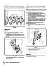
...back and forth between the R2 position and the F6 position several times. See Fig. 6-5. See Fig. 6-4. Maintenance & Adjustments Shut off the engine as follows: 1. Place the shift lever in the disengaged "up" position, the cable should NOT be in the shift lever. Loosen the .... The unit should not roll freely. 3. Proceed as instructed in the drive cable or if the snow thrower's drive is present in the separate engine manual. 2. Figure 6-5 3. Adjustments Figure 6-3 Drive Control When the drive control is in the cable. 4. With the drive control released, push the ...
...back and forth between the R2 position and the F6 position several times. See Fig. 6-5. See Fig. 6-4. Maintenance & Adjustments Shut off the engine as follows: 1. Place the shift lever in the disengaged "up" position, the cable should NOT be in the shift lever. Loosen the .... The unit should not roll freely. 3. Proceed as instructed in the drive cable or if the snow thrower's drive is present in the separate engine manual. 2. Figure 6-5 3. Adjustments Figure 6-3 Drive Control When the drive control is in the cable. 4. With the drive control released, push the ...
Operation Manual
Page 19
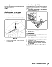
... rod. Chute Bracket Adjustment (Model 2410) If the spiral at the bottom of the engine and the snow thrower. Reinsert the cotter pin through this section. 3. Lubricate the machine as follows: 1. Section 6 - Chute Control Rod (Models 2620, 2840, y 3090XP) To adjust the chute control rod, proceed as instructed earlier in a clean, dry... to the chute assembly on the chute rotation assembly. 2. Loosen the two nuts which secure the chute bracket and reposition it stops due to the Engine Operator's Manual for 30 days or longer, follow the storage instructions below. 1.
... rod. Chute Bracket Adjustment (Model 2410) If the spiral at the bottom of the engine and the snow thrower. Reinsert the cotter pin through this section. 3. Lubricate the machine as follows: 1. Section 6 - Chute Control Rod (Models 2620, 2840, y 3090XP) To adjust the chute control rod, proceed as instructed earlier in a clean, dry... to the chute assembly on the chute rotation assembly. 2. Loosen the two nuts which secure the chute bracket and reposition it stops due to the Engine Operator's Manual for 30 days or longer, follow the storage instructions below. 1.
Operation Manual
Page 22
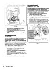
... must be replaced. To inspect the friction wheel, proceed as instructed on page 2 for information on ordering a Service Manual. Do not attempt to pour fuel from the engine. 2. Carefully pivot the snow thrower up and forward so that it rests on the auger housing. 4. Examine the... (F3) position. 3. See Fig. 7-8. 4. 6. Back out the stop bolt. See Fig. 7-7. Stop Bolt Friction Wheel Removal (Models 2410, 2620 & 2840) If the snow thrower fails to drive with the drive control engaged, and performing the drive control cable adjustment fails to correct the problem, the...
... must be replaced. To inspect the friction wheel, proceed as instructed on page 2 for information on ordering a Service Manual. Do not attempt to pour fuel from the engine. 2. Carefully pivot the snow thrower up and forward so that it rests on the auger housing. 4. Examine the... (F3) position. 3. See Fig. 7-8. 4. 6. Back out the stop bolt. See Fig. 7-7. Stop Bolt Friction Wheel Removal (Models 2410, 2620 & 2840) If the snow thrower fails to drive with the drive control engaged, and performing the drive control cable adjustment fails to correct the problem, the...


