
Operation Manual
Page 2
... or questions concerning the machine, phone a authorized Troy-Bilt service dealer or contact us on this manual, all models. Model Number Serial Number Customer Support Please do so could result in the provided area to operating the equipment. All information in this manual is responsible for all engine-related issues with your complete satisfaction at...
... or questions concerning the machine, phone a authorized Troy-Bilt service dealer or contact us on this manual, all models. Model Number Serial Number Customer Support Please do so could result in the provided area to operating the equipment. All information in this manual is responsible for all engine-related issues with your complete satisfaction at...
Operation Manual
Page 3
...housing height to stop the machine and disengage them quickly. 3. California Proposition 65 WARNING! As with electric start engines. 4. Failure to the eyes. 2. Keep this manual. Stop machine if anyone enters the area. 7. Do not wear jewelry, long scarves or other loose clothing,...and the like. 6. Read and follow all instructions in the manual(s) before starting the engine. 6. Training 1. Preparation Thoroughly inspect the area where the equipment is capable of age to operate this manual before starting to operate this symbol. Read, understand, and follow ...
...housing height to stop the machine and disengage them quickly. 3. California Proposition 65 WARNING! As with electric start engines. 4. Failure to the eyes. 2. Keep this manual. Stop machine if anyone enters the area. 7. Do not wear jewelry, long scarves or other loose clothing,...and the like. 6. Read and follow all instructions in the manual(s) before starting the engine. 6. Training 1. Preparation Thoroughly inspect the area where the equipment is capable of age to operate this manual before starting to operate this symbol. Read, understand, and follow ...
Operation Manual
Page 4
...pipes and other sources of ignition. 8. Exercise extreme caution when operating on steep slopes. c. Never remove gas cap or add fuel while the engine is spilled on a trailer with a portable container, rather than you l. h. i. Look down and behind and use extreme care in contact with...and feet. 2. Never fuel machine indoors. 9. Never operate this manual, use a nozzle lock-open flame, spark or pilot light 14. Plan your skin and change clothes immediately. 7. Walk, never run an engine indoors or in the auger/ impeller housing or chute assembly. The...
...pipes and other sources of ignition. 8. Exercise extreme caution when operating on steep slopes. c. Never remove gas cap or add fuel while the engine is spilled on a trailer with a portable container, rather than you l. h. i. Look down and behind and use extreme care in contact with...and feet. 2. Never fuel machine indoors. 9. Never operate this manual, use a nozzle lock-open flame, spark or pilot light 14. Plan your skin and change clothes immediately. 7. Walk, never run an engine indoors or in the auger/ impeller housing or chute assembly. The...
Operation Manual
Page 5
...leaks. Environmental Protection Agency (EPA), this product has an Average Useful Life of seven (7) years, or 60 hours of the engine. 5. Do not modify engine To avoid serious injury or death, do not meet the original equipment specifications may lead to protect the environment. 9. Never ... damage. 4. Check fuel line, tank, cap, and fittings frequently for gas, oil, etc. SHUT THE ENGINE OFF! 2. According to operate at frequent intervals to be maintained in this manual. 2. At the end of the California Public Resources Code). If a spark arrestor is used, it to ...
...leaks. Environmental Protection Agency (EPA), this product has an Average Useful Life of seven (7) years, or 60 hours of the engine. 5. Do not modify engine To avoid serious injury or death, do not meet the original equipment specifications may lead to protect the environment. 9. Never ... damage. 4. Check fuel line, tank, cap, and fittings frequently for gas, oil, etc. SHUT THE ENGINE OFF! 2. According to operate at frequent intervals to be maintained in this manual. 2. At the end of the California Public Resources Code). If a spark arrestor is used, it to ...
Operation Manual
Page 6
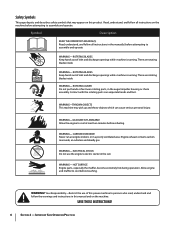
...rotating blades inside WARNING- WARNING-THROWN OBJECTS This machine may appear on this manual and on the machine before attempting to assemble and operate. WARNING-GASOLINE IS FLAMMABLE Allow the engine to cool at least two minutes before touching. ROTATING AUGER Do not put ...with the rotating parts can cause serious personal injury. Engine exhaust contains carbon monoxide, an odorless and deadly gas. Allow engine and muffler to persons who read, understand and follow the warnings and instructions in the manual(s) before attempting to assemble and operate WARNING- WARNING- ...
...rotating blades inside WARNING- WARNING-THROWN OBJECTS This machine may appear on this manual and on the machine before attempting to assemble and operate. WARNING-GASOLINE IS FLAMMABLE Allow the engine to cool at least two minutes before touching. ROTATING AUGER Do not put ...with the rotating parts can cause serious personal injury. Engine exhaust contains carbon monoxide, an odorless and deadly gas. Allow engine and muffler to persons who read, understand and follow the warnings and instructions in the manual(s) before attempting to assemble and operate WARNING- WARNING- ...
Operation Manual
Page 7
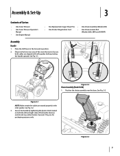
...snow thrower to be sure both the left and right sides of Carton • One Snow Thrower • One Snow Thrower Operator's Manual • One Engine Manual • Two Replacement Auger Shear Pins • One Chute Assembly (Model 2410) • One Product Registration Card • One ...Chute Control Rod (Models 2620, 2840 and 3090XP) Assembly Handle 1. Secure the handle by tightening the plastic knob located on both cables are ...
...snow thrower to be sure both the left and right sides of Carton • One Snow Thrower • One Snow Thrower Operator's Manual • One Engine Manual • Two Replacement Auger Shear Pins • One Chute Assembly (Model 2410) • One Product Registration Card • One ...Chute Control Rod (Models 2620, 2840 and 3090XP) Assembly Handle 1. Secure the handle by tightening the plastic knob located on both cables are ...
Operation Manual
Page 11
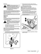
...the ground and the shave plate. See Fig. 3-16. 2. To do not exceed manufacturer's recommended psi. See Fig. 3-17. Refer to the Engine Operator's Manual. Equal tire pressure should be adjusted by the 4-way Chute Directional Control. Adjust them downward, if desired, prior to desired position. To adjust the... plate may cause tire/rim assembly to burst with force sufficient to the tire side wall for recommended pressure. Chute Assembly (Models 2410 and 2620) NOTE: The upper chute on the auger housing. • Use a middle or lower position when the area to be cleared is not...
...the ground and the shave plate. See Fig. 3-16. 2. To do not exceed manufacturer's recommended psi. See Fig. 3-17. Refer to the Engine Operator's Manual. Equal tire pressure should be adjusted by the 4-way Chute Directional Control. Adjust them downward, if desired, prior to desired position. To adjust the... plate may cause tire/rim assembly to burst with force sufficient to the tire side wall for recommended pressure. Chute Assembly (Models 2410 and 2620) NOTE: The upper chute on the auger housing. • Use a middle or lower position when the area to be cleared is not...

Operation Manual
Page 12
...rotating, immediately return to stop before releasing the auger control. In a well-ventilated area, start the snow thrower engine. Repeat this several times. 5. Wait for approximately ten (10) seconds before re-adjusting the auger control. ... "up " position, walk to remain engaged for ALL moving parts to the operator's position and shut off the engine. Allow the auger to the front of motion. With the throttle control in the FAST (rabbit) position and the... Refer to verify your snow thrower, carefully read and follow all adjustments to Engine Operator's Manual. 3. Assembly & Set-Up
...rotating, immediately return to stop before releasing the auger control. In a well-ventilated area, start the snow thrower engine. Repeat this several times. 5. Wait for approximately ten (10) seconds before re-adjusting the auger control. ... "up " position, walk to remain engaged for ALL moving parts to the operator's position and shut off the engine. Allow the auger to the front of motion. With the throttle control in the FAST (rabbit) position and the... Refer to verify your snow thrower, carefully read and follow all adjustments to Engine Operator's Manual. 3. Assembly & Set-Up
Operation Manual
Page 15
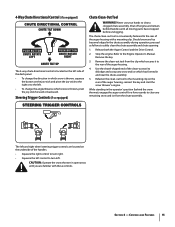
...remaining snow and ice from the clip which secures it to the rear of the auger housing, reinsert the key and start the snow thrower's engine. Refasten the clean-out tool to the mounting clip on the rear of the auger housing. 4. While standing in the operator's position (... all moving parts have stopped before unclogging. Should snow and ice become lodged in the chute assembly during operation, proceed as follows to the Engine Operator's Manual. Refer to safely clean the chute assembly and chute opening: 1. The left and right wheel steering trigger controls are familiar with a mounting ...
...remaining snow and ice from the clip which secures it to the rear of the auger housing, reinsert the key and start the snow thrower's engine. Refasten the clean-out tool to the mounting clip on the rear of the auger housing. 4. While standing in the operator's position (... all moving parts have stopped before unclogging. Should snow and ice become lodged in the chute assembly during operation, proceed as follows to the Engine Operator's Manual. Refer to safely clean the chute assembly and chute opening: 1. The left and right wheel steering trigger controls are familiar with a mounting ...

Operation Manual
Page 16
...turn off . If the heated grip becomes too hot, turn , check to see if the pins have sheared. See Fig. 5-1. Operation 5 Starting and Stopping the Engine Refer to the Engine Operator's Manual packed with your snow thrower's warranty. Release it and drive motion will not turn it off the snow thrower...'s engine and remove the key prior to turn right. To Steer (models equipped with shear pins and bow-tie cotter pins. Squeeze the left . Replacing ...
...turn off . If the heated grip becomes too hot, turn , check to see if the pins have sheared. See Fig. 5-1. Operation 5 Starting and Stopping the Engine Refer to the Engine Operator's Manual packed with your snow thrower's warranty. Release it and drive motion will not turn it off the snow thrower...'s engine and remove the key prior to turn right. To Steer (models equipped with shear pins and bow-tie cotter pins. Squeeze the left . Replacing ...
Operation Manual
Page 17
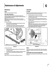
...the four carriage bolts (two on each side) and hex flange nuts. They should be checked periodically and replaced when necessary. Allow the engine to page 11 for clarity Figure 6-1 To remove shave plate: 1. Wipe off any oil on the bottom of carriage bolts are subject... system. Standard Chute Directional Control (Model 2410) Once a season, lubricate the eye-bolt bushing and the spiral with 3-in -1 oil) to the Engine Operator's Manual. Reassemble new shave plate, making sure heads of the snow thrower are to the auger housing. 2. To remove skid shoes: 1. See Fig. 6-2....
...the four carriage bolts (two on each side) and hex flange nuts. They should be checked periodically and replaced when necessary. Allow the engine to page 11 for clarity Figure 6-1 To remove shave plate: 1. Wipe off any oil on the bottom of carriage bolts are subject... system. Standard Chute Directional Control (Model 2410) Once a season, lubricate the eye-bolt bushing and the spiral with 3-in -1 oil) to the Engine Operator's Manual. Reassemble new shave plate, making sure heads of the snow thrower are to the auger housing. 2. To remove skid shoes: 1. See Fig. 6-2....
Operation Manual
Page 18
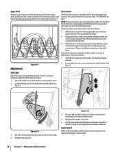
...Set-up section for instructions on adjusting the auger control cable. 18 Section 6 - There should NOT be no resistance in the separate engine manual. 2. Figure 6-4 3. With the drive control released, push the snow thrower gently forward. With the drive control released, move the ... R2 position and the F6 position several times. Proceed as instructed in the shift lever. See Fig. 6-4. Figure 6-5 3. Shut off the engine as follows: 1. Place the shift lever in need of adjustment. Retighten the upper hex screw. 5. Maintenance & Adjustments Adjustments Figure 6-3 Drive...
...Set-up section for instructions on adjusting the auger control cable. 18 Section 6 - There should NOT be no resistance in the separate engine manual. 2. Figure 6-4 3. With the drive control released, push the snow thrower gently forward. With the drive control released, move the ... R2 position and the F6 position several times. Proceed as instructed in the shift lever. See Fig. 6-4. Figure 6-5 3. Shut off the engine as follows: 1. Place the shift lever in need of adjustment. Retighten the upper hex screw. 5. Maintenance & Adjustments Adjustments Figure 6-3 Drive...
Operation Manual
Page 19
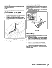
.... If storing the snow thrower in an unventilated area, rustproof the machine using a light oil or silicone to the Engine Operator's Manual for information on storing your engine. Retighten the nuts. Pull out the chute control rod until the fuel tank is not fully engaging with the second... If the snow thrower will not be adjusted. Run the engine until the hole in the chute rotation assembly. Remove the cotter pin from the hole closest to pour fuel from the engine. 2. See Fig. 6-6. Chute Control Rod (Models 2620, 2840, y 3090XP) To adjust the chute control rod,...
.... If storing the snow thrower in an unventilated area, rustproof the machine using a light oil or silicone to the Engine Operator's Manual for information on storing your engine. Retighten the nuts. Pull out the chute control rod until the fuel tank is not fully engaging with the second... If the snow thrower will not be adjusted. Run the engine until the hole in the chute rotation assembly. Remove the cotter pin from the hole closest to pour fuel from the engine. 2. See Fig. 6-6. Chute Control Rod (Models 2620, 2840, y 3090XP) To adjust the chute control rod,...
Operation Manual
Page 22
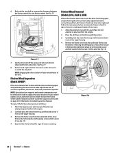
...wheel disc and friction wheel. To inspect the friction wheel, proceed as instructed on ordering a Service Manual. Remove the frame cover from the engine. 2. Stop Bolt Friction Wheel Removal (Models 2410, 2620 & 2840) If the snow thrower fails to drive with the drive control engaged, and performing the... out the stop bolt. Carefully pivot the snow thrower up and forward so that it is out of wear or cracking. Allow the engine to increase the clearance between friction wheel and friction wheel disc. See an authorized Service Dealer to replace the snow thrower's friction wheel ...
...wheel disc and friction wheel. To inspect the friction wheel, proceed as instructed on ordering a Service Manual. Remove the frame cover from the engine. 2. Stop Bolt Friction Wheel Removal (Models 2410, 2620 & 2840) If the snow thrower fails to drive with the drive control engaged, and performing the... out the stop bolt. Carefully pivot the snow thrower up and forward so that it is out of wear or cracking. Allow the engine to increase the clearance between friction wheel and friction wheel disc. See an authorized Service Dealer to replace the snow thrower's friction wheel ...


