Operation Manual
Page 2
... features discussed and/or illustrated in this entire manual prior to all times. Please be aware that you, and any other persons who will be found on the web at www.troybilt.com ◊ Call a Customer Support Representative at Troy-Bilt LLC • P.O. We want to right ...the recommended safety practices at the right rear of the machine are observed from the operating position. Table of this manual, all times. It was carefully engineered to do NOT return the unit to change product specifications, designs and equipment without notice and without first contacting our...
... features discussed and/or illustrated in this entire manual prior to all times. Please be aware that you, and any other persons who will be found on the web at www.troybilt.com ◊ Call a Customer Support Representative at Troy-Bilt LLC • P.O. We want to right ...the recommended safety practices at the right rear of the machine are observed from the operating position. Table of this manual, all times. It was carefully engineered to do NOT return the unit to change product specifications, designs and equipment without notice and without first contacting our...
Operation Manual
Page 3
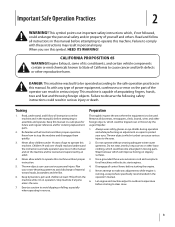
This symbol points out important safety instructions which, if not followed, could result in this manual before starting the engine. 5. DANGER: This machine was built to the eyes. 2. Thrown objects can cause serious injury to be trained and supervised by the auger/... attempt to make any type of power equipment, carelessness or error on the part of California to comply with any adjustments while engine is in the operator's manual. 6. Training 1. Keep bystanders, pets and children at least 75 feet from the machine while it is running, except where specifically...
This symbol points out important safety instructions which, if not followed, could result in this manual before starting the engine. 5. DANGER: This machine was built to the eyes. 2. Thrown objects can cause serious injury to be trained and supervised by the auger/... attempt to make any type of power equipment, carelessness or error on the part of California to comply with any adjustments while engine is in the operator's manual. 6. Training 1. Keep bystanders, pets and children at least 75 feet from the machine while it is running, except where specifically...
Operation Manual
Page 4
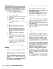
.... If possible, remove gas-powered equipment from your snow-throwing pattern to provide space for 3. Do not use care j. When starting engine, pull cord slowly until all cigarettes, cigars, pipes and other sources of ignition. 8. The auger/impeller control lever is an open...skin and change clothes immediately. 7. Never put hands or feet near rotating parts, in this manual, use care and good judgment. Do not unclog chute assembly while engine is not possible, then refuel such equipment on dryer etc.). slippery surfaces. Inspect thoroughly for hidden...
.... If possible, remove gas-powered equipment from your snow-throwing pattern to provide space for 3. Do not use care j. When starting engine, pull cord slowly until all cigarettes, cigars, pipes and other sources of ignition. 8. The auger/impeller control lever is an open...skin and change clothes immediately. 7. Never put hands or feet near rotating parts, in this manual, use care and good judgment. Do not unclog chute assembly while engine is not possible, then refuel such equipment on dryer etc.). slippery surfaces. Inspect thoroughly for hidden...
Operation Manual
Page 5
...Never tamper with factory setting of the California Public Resources Code). Important Safe Operation Practices 5 Wait 10 seconds to the operator's manual for proper tightness at unsafe speeds. Refer to the maintenance and adjustment sections of parts which are certified to comply with California ...inside where there is an open flame, spark or pilot light such as necessary. 8. Always use your hands. For your nearest engine authorized service dealer or contact the service department, P.O. This machine is equipped with the governor setting can result in safe working ...
...Never tamper with factory setting of the California Public Resources Code). Important Safe Operation Practices 5 Wait 10 seconds to the operator's manual for proper tightness at unsafe speeds. Refer to the maintenance and adjustment sections of parts which are certified to comply with California ...inside where there is an open flame, spark or pilot light such as necessary. 8. Always use your hands. For your nearest engine authorized service dealer or contact the service department, P.O. This machine is equipped with the governor setting can result in safe working ...
Operation Manual
Page 6
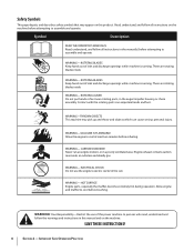
... all instructions on the machine. WARNING-THROWN OBJECTS This machine may appear on this manual and on the machine before attempting to assemble and operate. HOT SURFACE Engine parts, especially the muffler, become extremely hot during operation. Allow engine and muffler to cool at least two minutes before touching. ROTATING AUGER Do not...
... all instructions on the machine. WARNING-THROWN OBJECTS This machine may appear on this manual and on the machine before attempting to assemble and operate. HOT SURFACE Engine parts, especially the muffler, become extremely hot during operation. Allow engine and muffler to cool at least two minutes before touching. ROTATING AUGER Do not...
Operation Manual
Page 7
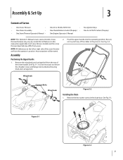
... 1. Wing Knob Carriage Bolts Wing Knob Figure 3-2 Installing the Chute 1. Bottle 5W-30 Oil • One Chute Rotation Control (If equip.) • One Engine Operator's Manual Two Ignition Keys One Set of Carton • One Snow Thrower • • One Chute Assembly • • One Snow Thrower Operator...; One 20 oz. NOTE: All references to the left or right side of the snow thrower are applicable to all features in this manual are from the top of the cables in the chute base. Remove the wing knob and carriage bolt from the operator's position. See Fig. 3-1....
... 1. Wing Knob Carriage Bolts Wing Knob Figure 3-2 Installing the Chute 1. Bottle 5W-30 Oil • One Chute Rotation Control (If equip.) • One Engine Operator's Manual Two Ignition Keys One Set of Carton • One Snow Thrower • • One Chute Assembly • • One Snow Thrower Operator...; One 20 oz. NOTE: All references to the left or right side of the snow thrower are applicable to all features in this manual are from the top of the cables in the chute base. Remove the wing knob and carriage bolt from the operator's position. See Fig. 3-1....

Operation Manual
Page 9
See Fig. 3-7. 5. Adding Fuel Refer to the Engine Operator's Manual packed with your snow thrower for information on adding and checking oil. 3. Securely tighten the eye bolt and handle knob. Assembly & Set-Up 9 Section 3 - Slip the recoil starter rope into the eye bolt from the back of the snow thrower. Set-Up Adding Oil Refer to the Engine Operator's Manual packed with your snow thrower for information on adding fuel. Slowly pull the recoil starter handle up towards the eye bolt. 4.
See Fig. 3-7. 5. Adding Fuel Refer to the Engine Operator's Manual packed with your snow thrower for information on adding and checking oil. 3. Securely tighten the eye bolt and handle knob. Assembly & Set-Up 9 Section 3 - Slip the recoil starter rope into the eye bolt from the back of the snow thrower. Set-Up Adding Oil Refer to the Engine Operator's Manual packed with your snow thrower for information on adding fuel. Slowly pull the recoil starter handle up towards the eye bolt. 4.
Operation Manual
Page 10
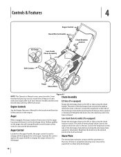
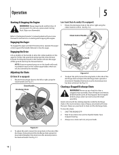
... side of the discharge chute controls the angle at which the snow is used to be discharged. 10 The pitch of See the Engine Operator's Manual for the location and function the discharge chute before pivoting the discharge chute Auger Control upward or downward. engage and disengage drive to... features in contact with the pavement as they come in this Chute Assembly manual are applicable to the left or right using the chute rotation control. Retighten the knob once the desired Located on the engine. release it out the discharge chute. Retighten the knob once the desired ...
... side of the discharge chute controls the angle at which the snow is used to be discharged. 10 The pitch of See the Engine Operator's Manual for the location and function the discharge chute before pivoting the discharge chute Auger Control upward or downward. engage and disengage drive to... features in contact with the pavement as they come in this Chute Assembly manual are applicable to the left or right using the chute rotation control. Retighten the knob once the desired Located on the engine. release it out the discharge chute. Retighten the knob once the desired ...

Operation Manual
Page 11
... the snow thrower. To rotate the chute to the left . Maneuver the snow thrower so that the cutters penetrate a high standing snow drift to manually start the engine. Drift Cutters (If so Equipped) The drift cutters are designed for normal snow conditions. Section 4 - Recoil Starter Handle The recoil starter handle is used...
... the snow thrower. To rotate the chute to the left . Maneuver the snow thrower so that the cutters penetrate a high standing snow drift to manually start the engine. Drift Cutters (If so Equipped) The drift cutters are designed for normal snow conditions. Section 4 - Recoil Starter Handle The recoil starter handle is used...
Operation Manual
Page 12
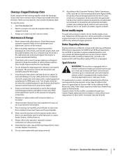
... Discharge Chute Wing Knob Figure 5-2 2. Clearing a Clogged Discharge Chute WARNING! Wait 10 seconds to clear the chute assembly. Rotate the discharge chute to the Engine Operator's manual packed with snow throwers. Refer to the left or right using the chute rotation control. To adjust the pitch, loosen the wing knob on the...
... Discharge Chute Wing Knob Figure 5-2 2. Clearing a Clogged Discharge Chute WARNING! Wait 10 seconds to clear the chute assembly. Rotate the discharge chute to the Engine Operator's manual packed with snow throwers. Refer to the left or right using the chute rotation control. To adjust the pitch, loosen the wing knob on the...
Operation Manual
Page 13
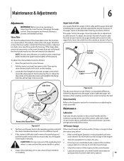
... auger drive belt stretching due to wear, periodic adjustments may be adjusted. If the auger seems to see if it is difficult to the Engine Operator's manual packed with a light oil. 13 To adjust, disconnect the end of the control cable with a new shave plate installed, the auger may... come out of the engine and the snow thrower. 6. Insert the cable from the snow thrower. 2. Control Handle Control Cable Side View Carriage Screw Flange Lock ...
... auger drive belt stretching due to wear, periodic adjustments may be adjusted. If the auger seems to see if it is difficult to the Engine Operator's manual packed with a light oil. 13 To adjust, disconnect the end of the control cable with a new shave plate installed, the auger may... come out of the engine and the snow thrower. 6. Insert the cable from the snow thrower. 2. Control Handle Control Cable Side View Carriage Screw Flange Lock ...
Operation Manual
Page 14
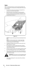
...pull back. Inspect the spark plug. CAUTION: Oil may come out of the panel has tabs that help hold it in place. Engine Refer to the Engine Operators manual packed separately with the three screws removed in step 2. 5. Remove the lower panel by placing the tabs in the tab slots, ...extension kit is pulled. 7. Change the oil and/or the spark plug as instructed in the head is removed. Contact your local Troy-Bilt dealer or contact Troy-Bilt's Customer Support for maintenance and adjustment information on model 2T5 it is difficult to pull, remove the spark plug and pull the handle...
...pull back. Inspect the spark plug. CAUTION: Oil may come out of the panel has tabs that help hold it in place. Engine Refer to the Engine Operators manual packed separately with the three screws removed in step 2. 5. Remove the lower panel by placing the tabs in the tab slots, ...extension kit is pulled. 7. Change the oil and/or the spark plug as instructed in the head is removed. Contact your local Troy-Bilt dealer or contact Troy-Bilt's Customer Support for maintenance and adjustment information on model 2T5 it is difficult to pull, remove the spark plug and pull the handle...


