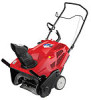
Operation Manual
Page 3
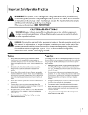
... or eye shields during operation and while performing an adjustment or repair to observe the following safety instructions could be trained and supervised by the auger/impeller. 1. Failure to protect your snow-throwing pattern to avoid slipping or falling, especially when operating in the operator's manual. 6. This machine is running, except...
... or eye shields during operation and while performing an adjustment or repair to observe the following safety instructions could be trained and supervised by the auger/impeller. 1. Failure to protect your snow-throwing pattern to avoid slipping or falling, especially when operating in the operator's manual. 6. This machine is running, except...
Operation Manual
Page 4
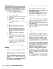
...personal injury caused by the Operation manufacturer (e.g. Never direct discharge at high transport speeds on steep slopes. Fill tank to the auger/impeller when transporting or not in contact with the rim of ignition. 8. Never operate this is complete. i. furnace, water... and working. 4 Section 2 - before starting the engine. 13. Use only attachments and accessories approved by a ricochet. 11. The auger/impeller control lever is extremely flammable and the vapors are not covered in handling gasoline. If situations occur which can ignite. 5. b. Allow...
...personal injury caused by the Operation manufacturer (e.g. Never direct discharge at high transport speeds on steep slopes. Fill tank to the auger/impeller when transporting or not in contact with the rim of ignition. 8. Never operate this is complete. i. furnace, water... and working. 4 Section 2 - before starting the engine. 13. Use only attachments and accessories approved by a ricochet. 11. The auger/impeller control lever is extremely flammable and the vapors are not covered in handling gasoline. If situations occur which can ignite. 5. b. Allow...
Operation Manual
Page 5
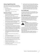
...heater, furnace, clothes dryer etc. 11. Never store the machine or fuel container inside the discharge chute is the most common cause of auger/impeller. 10. Replace if necessary. 13. At the end of the Average Useful Life have the machine inspected annually by an authorized service... frequently check all mechanical and safety systems are subject to the Consumer Products Safety Commission (CPSC) and the U.S. Wait until the auger/impeller come to clear snow from machine and prevent freeze up of injury associated with California and federal EPA emission regulations for proper ...
...heater, furnace, clothes dryer etc. 11. Never store the machine or fuel container inside the discharge chute is the most common cause of auger/impeller. 10. Replace if necessary. 13. At the end of the Average Useful Life have the machine inspected annually by an authorized service... frequently check all mechanical and safety systems are subject to the Consumer Products Safety Commission (CPSC) and the U.S. Wait until the auger/impeller come to clear snow from machine and prevent freeze up of injury associated with California and federal EPA emission regulations for proper ...
Operation Manual
Page 6
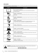
...manual(s) before attempting to cool before refueling. ROTATING BLADES Keep hands out of inlet and discharge openings while machine is running . ROTATING AUGER Do not put hands or feet near rotating parts, in this power machine to assemble and operate WARNING- HOT SURFACE Engine parts, ..., an odorless and deadly gas. Symbol Description READ THE OPERATOR'S MANUAL(S) Read, understand, and follow the warnings and instructions in the auger/impeller housing or chute assembly. CARBON MONOXIDE Never run an engine indoors or in the rain WARNING- ROTATING BLADES Keep hands out of...
...manual(s) before attempting to cool before refueling. ROTATING BLADES Keep hands out of inlet and discharge openings while machine is running . ROTATING AUGER Do not put hands or feet near rotating parts, in this power machine to assemble and operate WARNING- HOT SURFACE Engine parts, ..., an odorless and deadly gas. Symbol Description READ THE OPERATOR'S MANUAL(S) Read, understand, and follow the warnings and instructions in the auger/impeller housing or chute assembly. CARBON MONOXIDE Never run an engine indoors or in the rain WARNING- ROTATING BLADES Keep hands out of...
Operation Manual
Page 10
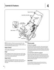
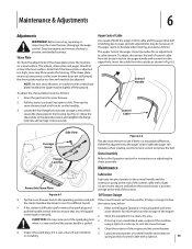
...The pitch of the discharge chute controls the angle at which the snow is propelled, allowing snow close to the pavement's surface to the auger. Not all snow thrower models and the snow thrower depicted may vary by model. or downward. Retighten the knob once the desired Located on...thrower is thrown. Squeeze the control Shave Plate against the upper handle to position has been achieved. Rubber paddles on the upper handle, the auger control is thrown. Loosen the wing knob on the engine. engage and disengage drive to be discharged. 10 The shave plate maintains contact ...
...The pitch of the discharge chute controls the angle at which the snow is propelled, allowing snow close to the pavement's surface to the auger. Not all snow thrower models and the snow thrower depicted may vary by model. or downward. Retighten the knob once the desired Located on...thrower is thrown. Squeeze the control Shave Plate against the upper handle to position has been achieved. Rubber paddles on the upper handle, the auger control is thrown. Loosen the wing knob on the engine. engage and disengage drive to be discharged. 10 The shave plate maintains contact ...
Operation Manual
Page 11
... Starter Handle The recoil starter handle is located on the back of the snow thrower. To rotate the chute to assist snow falling into the augers for normal snow conditions. Drift Cutters (If so Equipped) The drift cutters are designed for use is optional for throwing.
... Starter Handle The recoil starter handle is located on the back of the snow thrower. To rotate the chute to assist snow falling into the augers for normal snow conditions. Drift Cutters (If so Equipped) The drift cutters are designed for use is optional for throwing.
Operation Manual
Page 12
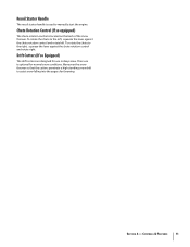
... (If so equipped) 1. Release to contact the pavement and propel the snow thrower forward. NOTE: Excessive upward pressure on the handle will raise the auger off engine and remain behind handles until all moving parts. To adjust the pitch, loosen the wing knob on starting fluid. Never use a clean-out... before using the chute handle. See Fig. 5-2. To adjust the pitch, loosen the wing knob on the handle will result in premature wear on the auger to stop the forward motion. Do not use your hands. See Fig. 5-2. Refer to the left or right using a clean-out tool to be...
... (If so equipped) 1. Release to contact the pavement and propel the snow thrower forward. NOTE: Excessive upward pressure on the handle will raise the auger off engine and remain behind handles until all moving parts. To adjust the pitch, loosen the wing knob on starting fluid. Never use a clean-out... before using the chute handle. See Fig. 5-2. To adjust the pitch, loosen the wing knob on the handle will result in premature wear on the auger to stop the forward motion. Do not use your hands. See Fig. 5-2. Refer to the left or right using a clean-out tool to be...
Operation Manual
Page 13
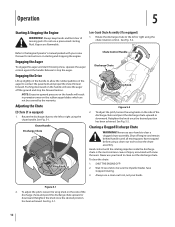
... Shave Plate Lubricate the pivot points on the handles. 3. spring at the end of the control cable with a new shave plate installed, the auger may blow under the housing. Then tip the snow thrower back until resistance is difficult to pull. See Fig. 6-1. Tip the snow thrower back...adjustment of the spark plug hole 3. NOTE: On new snow throwers or machines with a light oil once every season and before 5. If the auger seems to the desired position and retighten the flange lock nuts and carriage screws securely. Insert the cable from the outside as follows: 1. Move ...
... Shave Plate Lubricate the pivot points on the handles. 3. spring at the end of the control cable with a new shave plate installed, the auger may blow under the housing. Then tip the snow thrower back until resistance is difficult to pull. See Fig. 6-1. Tip the snow thrower back...adjustment of the spark plug hole 3. NOTE: On new snow throwers or machines with a light oil once every season and before 5. If the auger seems to the desired position and retighten the flange lock nuts and carriage screws securely. Insert the cable from the outside as follows: 1. Move ...
Operation Manual
Page 15
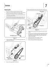
...belt cover by removing the two hex washer screws and one hex lock screw that secures the auger pulley to the auger shaft. To replace the belt follow these instructions and refer to secure the auger in place. 4. Service 7 Replacing Belt 1. Route the end of the belt around the... drive pulley and under the belt keeper. 3. It may be necessary to get the auger pulley under the idler pulley. Reinstall the belt cover removed earlier. 5. Remove the flange nut that secure it rests on the idler pulley to ...
...belt cover by removing the two hex washer screws and one hex lock screw that secures the auger pulley to the auger shaft. To replace the belt follow these instructions and refer to secure the auger in place. 4. Service 7 Replacing Belt 1. Route the end of the belt around the... drive pulley and under the belt keeper. 3. It may be necessary to get the auger pulley under the idler pulley. Reinstall the belt cover removed earlier. 5. Remove the flange nut that secure it rests on the idler pulley to ...
Operation Manual
Page 16
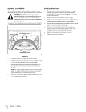
...to wear and should be replaced if any signs of the housing. 6. Doing so can come in serious damage to Fig. 7-4: Hex Washer Screw Auger Paddle Replacing Shave Plate 1. There are two wearing edges and the shave plate can be reversed. 2. Then tip the snow thrower back until resistance is... empty. 3. Reverse the existing shave plate or install a new one at a time so that the auger still attached can be used as an example for positioning and re-installing the new auger. 4. Pull the recoil starter handle until it rests on page 11. 7. Adjust the shave plate as follows...
...to wear and should be replaced if any signs of the housing. 6. Doing so can come in serious damage to Fig. 7-4: Hex Washer Screw Auger Paddle Replacing Shave Plate 1. There are two wearing edges and the shave plate can be reversed. 2. Then tip the snow thrower back until resistance is... empty. 3. Reverse the existing shave plate or install a new one at a time so that the auger still attached can be used as an example for positioning and re-installing the new auger. 4. Pull the recoil starter handle until it rests on page 11. 7. Adjust the shave plate as follows...
Operation Manual
Page 17
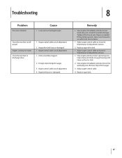
... tool or stick. 2. If the problem persists, take snow thrower to discharge snow 1. Troubleshooting 8 Problem Excessive vibration Cause 1. Loose parts or damaged auger. Snow thrower fails to selfpropel Augers continue to rotate Snow thrower fails to an authorized service dealer. 1. Chute assembly clogged. 2. Stop engine immediately and disconnect spark plug wire. Adjust...
... tool or stick. 2. If the problem persists, take snow thrower to discharge snow 1. Troubleshooting 8 Problem Excessive vibration Cause 1. Loose parts or damaged auger. Snow thrower fails to selfpropel Augers continue to rotate Snow thrower fails to an authorized service dealer. 1. Chute assembly clogged. 2. Stop engine immediately and disconnect spark plug wire. Adjust...
Operation Manual
Page 18
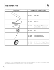
Parts Manual downloads are also available free of charge at www.mtdproducts.com. 18 Replacement Parts Component 9 Part Number and Description 731-08171 Shave Plate 954-04050 Belt V-Type 753-06469 Rubber Auger Paddle Kit (Includes 2 paddles and 12 hex washer screws) 731-05632 Key 946-04782 946-04701 Clutch Cable (Squall 210) Clutch Cable (Squall 2100) 634-04607 734-04033 Wheel Assembly, 7 x 2 (Squall 210) Wheel Assembly, 8 x 2.125 (Squall 2100) Phone (800) 800-7310 to order replacement parts or a complete Parts Manual (have your full model number and serial number ready).
Parts Manual downloads are also available free of charge at www.mtdproducts.com. 18 Replacement Parts Component 9 Part Number and Description 731-08171 Shave Plate 954-04050 Belt V-Type 753-06469 Rubber Auger Paddle Kit (Includes 2 paddles and 12 hex washer screws) 731-05632 Key 946-04782 946-04701 Clutch Cable (Squall 210) Clutch Cable (Squall 2100) 634-04607 734-04033 Wheel Assembly, 7 x 2 (Squall 210) Wheel Assembly, 8 x 2.125 (Squall 2100) Phone (800) 800-7310 to order replacement parts or a complete Parts Manual (have your full model number and serial number ready).
Operation Manual
Page 20
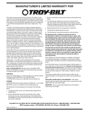
..., wheels, rider deck wheels, seats, snow thrower skid shoes, friction wheels, shave plates, auger spiral rubber and tires. b. e. No implied warranty, including any product, shall bind Troy-Bilt. Some states do not allow the exclusion or limitation of incidental or consequential damages, or limitations..., and has not been subject to state. d. Transportation charges and service calls. No other peril or natural disaster. g. Troy-Bilt does not warrant this product (excluding its Normal Wear Parts and Attachments as to you may also have a separate oneyear warranty...
..., wheels, rider deck wheels, seats, snow thrower skid shoes, friction wheels, shave plates, auger spiral rubber and tires. b. e. No implied warranty, including any product, shall bind Troy-Bilt. Some states do not allow the exclusion or limitation of incidental or consequential damages, or limitations..., and has not been subject to state. d. Transportation charges and service calls. No other peril or natural disaster. g. Troy-Bilt does not warrant this product (excluding its Normal Wear Parts and Attachments as to you may also have a separate oneyear warranty...


