
Operation Manual
Page 17
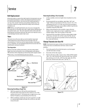
...engage the bail and hold it so that secure the tine assembly to Fig. 7-1 for ordering information. The tines can be replaced either individually or as the tiller moves forward. If necessary, use penetrating oil on a tine holder. 2. Service 7 Belt Replacement If the drive belt... to the tine shaft using the screw and locknut. A tine assembly consists of tilling depth, and reduced effectiveness when chopping up and turning under the belt keeping mechanism built into the belt cover. Rear/Operator Removing/Installing a Tine Assembly: 1. Secure the tine assembly to ...
...engage the bail and hold it so that secure the tine assembly to Fig. 7-1 for ordering information. The tines can be replaced either individually or as the tiller moves forward. If necessary, use penetrating oil on a tine holder. 2. Service 7 Belt Replacement If the drive belt... to the tine shaft using the screw and locknut. A tine assembly consists of tilling depth, and reduced effectiveness when chopping up and turning under the belt keeping mechanism built into the belt cover. Rear/Operator Removing/Installing a Tine Assembly: 1. Secure the tine assembly to ...
Service Manual
Page 5
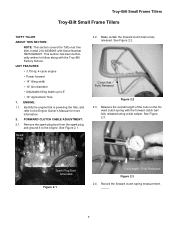
... • Adjustable tilling depth up to follow along with the Troy-Bilt Factory School. ward clutch spring with Serial Number 1B212G80447. See Figure 2.3. Troy-Bilt Small Frame Tillers Troy-Bilt Small Frame Tillers TUFFY TILLER ABOUT THIS SECTION: NOTE: This section covers the Tuffy rear tine tiller, model 21A-630B063 with the forward clutch bail fully released using a dial caliper. Spark Plug...
... • Adjustable tilling depth up to follow along with the Troy-Bilt Factory School. ward clutch spring with Serial Number 1B212G80447. See Figure 2.3. Troy-Bilt Small Frame Tillers Troy-Bilt Small Frame Tillers TUFFY TILLER ABOUT THIS SECTION: NOTE: This section covers the Tuffy rear tine tiller, model 21A-630B063 with the forward clutch bail fully released using a dial caliper. Spark Plug...
Service Manual
Page 15
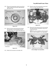
... assembly. Remove the hex screws and lock nuts securing the right and left tine assemblies using a 1/2" socket. See Image Below Left Right Shoulder Washer Lock Washer Hex Screw Figure 6.31 Idler Pulley 6.32. Transmission Pulley Key Belleville Troy-Bilt Small Frame Tillers 6.33. Remove the hex screw securing the forward idler assembly to the... Nut Hex Screw & Lock Nut Front Support Washer Hex Screw Figure 6.30 6.31. See Figure 6.30. Rotate the transmission horizontally 180°. 6.30. Raise the rear of the tine assemblies for correct installation.
... assembly. Remove the hex screws and lock nuts securing the right and left tine assemblies using a 1/2" socket. See Image Below Left Right Shoulder Washer Lock Washer Hex Screw Figure 6.31 Idler Pulley 6.32. Transmission Pulley Key Belleville Troy-Bilt Small Frame Tillers 6.33. Remove the hex screw securing the forward idler assembly to the... Nut Hex Screw & Lock Nut Front Support Washer Hex Screw Figure 6.30 6.31. See Figure 6.30. Rotate the transmission horizontally 180°. 6.30. Raise the rear of the tine assemblies for correct installation.
Service Manual
Page 17
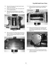
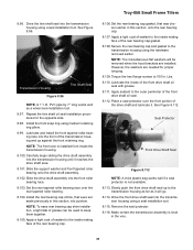
... 180° to the transmission housing assembly using a 1/2" socket. Wheel Worm Cover Gasket Troy-Bilt Small Frame Tillers 7.10. Remove the rear transmission cover gasket from the transmission case assembly. 7.7. Remove the remaining lower hex flange screw securing the.... 7.8. See Figure 7.9. Rear Bearing Cap Transmission Overlap Point Rear Transmission Cover Figure 7.9 Short Hex Flange Screw Figure 7.11 7.12. Break the rear bearing cap free from the transmission using a punch and hammer. 13 7.6. See Figure 7.8. Cover Gasket Tine Worm Figure 7.8 7.9. Hex...
... 180° to the transmission housing assembly using a 1/2" socket. Wheel Worm Cover Gasket Troy-Bilt Small Frame Tillers 7.10. Remove the rear transmission cover gasket from the transmission case assembly. 7.7. Remove the remaining lower hex flange screw securing the.... 7.8. See Figure 7.9. Rear Bearing Cap Transmission Overlap Point Rear Transmission Cover Figure 7.9 Short Hex Flange Screw Figure 7.11 7.12. Break the rear bearing cap free from the transmission using a punch and hammer. 13 7.6. See Figure 7.8. Cover Gasket Tine Worm Figure 7.8 7.9. Hex...
Service Manual
Page 35
... transmission housing and up to 100 In. Transmission Housing Tine Shaft Seal Figure 8.96 NOTE: A 1" I.D. Lbs. 8.110. Drive the tine shaft seal into position. Carefully begin sliding the drive shaft assembly into the front roller bearing race. 8.103. Troy-Bilt Small Frame Tillers 8.96. Set the rear tapered roller bearing race over the front portion of...
... transmission housing and up to 100 In. Transmission Housing Tine Shaft Seal Figure 8.96 NOTE: A 1" I.D. Lbs. 8.110. Drive the tine shaft seal into position. Carefully begin sliding the drive shaft assembly into the front roller bearing race. 8.103. Troy-Bilt Small Frame Tillers 8.96. Set the rear tapered roller bearing race over the front portion of...


