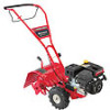
Operation Manual
Page 4
... the tines at high transport speeds on or crossing gravel surfaces. Do not carry passengers. 7. Start the engine according to prevent unintended starting and operating. 18. Repair the damage before starting and operating. 12. Disengage all times. 11. Rotating tines can result in operation. Keep all times until the tines come...
... the tines at high transport speeds on or crossing gravel surfaces. Do not carry passengers. 7. Start the engine according to prevent unintended starting and operating. 18. Repair the damage before starting and operating. 12. Disengage all times. 11. Rotating tines can result in operation. Keep all times until the tines come...
Operation Manual
Page 7
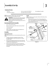
... NOTE: This Operator's Manual covers several garden tiller models. Remove two hex screws (5⁄16-18 x 1.50), two flange lock nuts (5⁄16-18), carriage bolt (5⁄16-18 x 6.75), bell washer (.326 x .875 x .145) and knob (5⁄16-18) from the shipping platform. 3. WARNING! To prevent personal injury or property damage, do not...
... NOTE: This Operator's Manual covers several garden tiller models. Remove two hex screws (5⁄16-18 x 1.50), two flange lock nuts (5⁄16-18), carriage bolt (5⁄16-18 x 6.75), bell washer (.326 x .875 x .145) and knob (5⁄16-18) from the shipping platform. 3. WARNING! To prevent personal injury or property damage, do not...
Operation Manual
Page 8
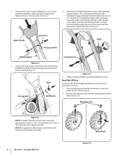
... the desired setting, push the carriage screw in the handlebar support bracket. Use a setting that will not move, loosen the attaching hex screws (5⁄16-18 x .75) and flange lock nuts (5⁄1618) at approximately waist level when the tines are three height adjustment holes in until the square portion of...
... the desired setting, push the carriage screw in the handlebar support bracket. Use a setting that will not move, loosen the attaching hex screws (5⁄16-18 x .75) and flange lock nuts (5⁄1618) at approximately waist level when the tines are three height adjustment holes in until the square portion of...
Operation Manual
Page 18
... 7- Remove all dirt and clean the area around the transmission cover. See Fig. 7-3 6. Service Remove the four hex screws (5⁄16-18 x .75) securing the transmission cover to drain through the top of the transmission. 7. Refill the transmission using Mobil 1® Synthetic 75W 140. Refill the engine ...
... 7- Remove all dirt and clean the area around the transmission cover. See Fig. 7-3 6. Service Remove the four hex screws (5⁄16-18 x .75) securing the transmission cover to drain through the top of the transmission. 7. Refill the transmission using Mobil 1® Synthetic 75W 140. Refill the engine ...
Service Manual
Page 13
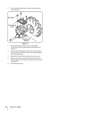
... setting on the ground. 9 Lower the front of hex screws securing the left engine bracket using needle nose pliers. See Figure 6.17. Troy-Bilt Small Frame Tillers 6.20. Pivot the forward idler lever inward. 6.19. Upper Handlebar Secured Transmission Figure 6.20 Engine Bracket 6.21. Self... 6.19 NOTE: The unit needs to the transmission using a 1/2" socket. Idler Lever Right Engine Bracket Hex Screws Return Spring Figure 6.17 6.18. See Figure 6.21. Remove the forward return spring from above. Secure the upper handlebar in position from the right engine bracket using a 3/8"...
... setting on the ground. 9 Lower the front of hex screws securing the left engine bracket using needle nose pliers. See Figure 6.17. Troy-Bilt Small Frame Tillers 6.20. Pivot the forward idler lever inward. 6.19. Upper Handlebar Secured Transmission Figure 6.20 Engine Bracket 6.21. Self... 6.19 NOTE: The unit needs to the transmission using a 1/2" socket. Idler Lever Right Engine Bracket Hex Screws Return Spring Figure 6.17 6.18. See Figure 6.21. Remove the forward return spring from above. Secure the upper handlebar in position from the right engine bracket using a 3/8"...

Service Manual
Page 18
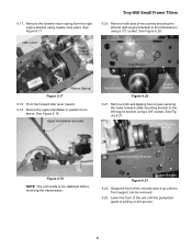
... Figure 7.17. See Figure 7.22. See Figure 7.13. NOTE: Use gasket eliminator during assembly. 7.17. NOTE: This is a rear bearing cap gasket. Troy-Bilt Small Frame Tillers 7.13. Shims Figure 7.18 7.19. Dial Caliper Transmission Housing Rear Bearing Cap Figure 7.13 7.14. NOTE: There are different thickness rear bearing cap gaskets available to...
... Figure 7.17. See Figure 7.22. See Figure 7.13. NOTE: Use gasket eliminator during assembly. 7.17. NOTE: This is a rear bearing cap gasket. Troy-Bilt Small Frame Tillers 7.13. Shims Figure 7.18 7.19. Dial Caliper Transmission Housing Rear Bearing Cap Figure 7.13 7.14. NOTE: There are different thickness rear bearing cap gaskets available to...
Service Manual
Page 22
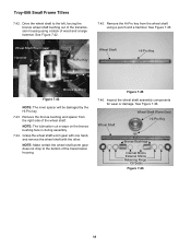
... Shaft Hi-Pro Key Spacer Bronze Bushing Figure 7.42 NOTE: The inner spacer will be damaged by the Hi-Pro key. 7.43. See Figure 7.45. Troy-Bilt Small Frame Tillers 7.42. Remove the bronze bushing and spacer from the wheel shaft using a block of the wheel shaft. Wheel Shaft Wheel Shaft Worm... Gear Hi-Pro Key Bronze Bushings Internal Shims External Shims Retaining Rings Oil Seals Figure 7.46 18 Figure 7.45 7.46. Remove the Hi-Pro key from the right side of wood and a large hammer. See Figure 7.46. Grasp the wheel shaft ...
... Shaft Hi-Pro Key Spacer Bronze Bushing Figure 7.42 NOTE: The inner spacer will be damaged by the Hi-Pro key. 7.43. See Figure 7.45. Troy-Bilt Small Frame Tillers 7.42. Remove the bronze bushing and spacer from the wheel shaft using a block of the wheel shaft. Wheel Shaft Wheel Shaft Worm... Gear Hi-Pro Key Bronze Bushings Internal Shims External Shims Retaining Rings Oil Seals Figure 7.46 18 Figure 7.45 7.46. Remove the Hi-Pro key from the right side of wood and a large hammer. See Figure 7.46. Grasp the wheel shaft ...
Service Manual
Page 28
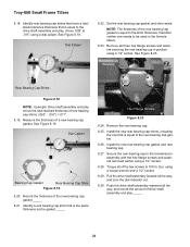
... 8.19. Remove the rear bearing cap. 8.25. Secure the rear bearing cap to 100 In. Troy-Bilt Small Frame Tillers 8.18. See Figure 8.18. Hex Flange Screws Figure 8.23 8.24. Dial Caliper 8.22. Miscellaneous Washers Rear Bearing Cap Shims Figure 8.18 NOTE: Example: Drive shaft assembly end play _____. 24 using a 1/2" socket. 8.28. NOTE: The...
... 8.19. Remove the rear bearing cap. 8.25. Secure the rear bearing cap to 100 In. Troy-Bilt Small Frame Tillers 8.18. See Figure 8.18. Hex Flange Screws Figure 8.23 8.24. Dial Caliper 8.22. Miscellaneous Washers Rear Bearing Cap Shims Figure 8.18 NOTE: Example: Drive shaft assembly end play _____. 24 using a 1/2" socket. 8.28. NOTE: The...