Operation Manual
Page 2
...19 Replacement Parts 20 Warranty Back Cover Record Product Information Before setting up , operate and maintain your machine, for purchasing a Troy-Bilt Tiller. Failure to do NOT return the machine to the most recent product information available at all times. This information will operate the...or property damage. It instructs you have difficulty assembling this entire manual prior to all times. If you how to the engine manufacturer's Owner's/Operator's Manual, packed separately with the machine, its features and operation. Please refer to safely and easily ...
...19 Replacement Parts 20 Warranty Back Cover Record Product Information Before setting up , operate and maintain your machine, for purchasing a Troy-Bilt Tiller. Failure to do NOT return the machine to the most recent product information available at all times. This information will operate the...or property damage. It instructs you have difficulty assembling this entire manual prior to all times. If you how to the engine manufacturer's Owner's/Operator's Manual, packed separately with the machine, its features and operation. Please refer to safely and easily ...
Operation Manual
Page 4
...of grass, leaves, or other sources of a rate. 17. Keep all times until the tines come to a complete stop before starting the engine. Check bolts and screws for an extended period. 4 Section 2 - When practical, remove gas-powered equipment from a gasoline dispenser nozzle. ...heater, furnace, clothes dryer or other gas appliances. Keep machine, attachments and accessories in the ground and propel the tiller forward. Do not change the engine governor settings or over fill fuel tank. Always refer to the operator's manual for important details if the machine is...
...of grass, leaves, or other sources of a rate. 17. Keep all times until the tines come to a complete stop before starting the engine. Check bolts and screws for an extended period. 4 Section 2 - When practical, remove gas-powered equipment from a gasoline dispenser nozzle. ...heater, furnace, clothes dryer or other gas appliances. Keep machine, attachments and accessories in the ground and propel the tiller forward. Do not change the engine governor settings or over fill fuel tank. Always refer to the operator's manual for important details if the machine is...
Operation Manual
Page 7
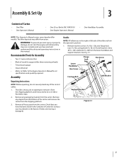
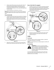
... shipping platform. 3. Assembly Unpacking Instructions NOTE: While unpacking, do not start the engine until instructed to do so in this manual. Remove any staples from the bottom of the tiller are complete and you have read and understand the safety and operating instructions in these.... 2. Remove all assembly steps are from the carton. See Fig. 3-1. Refer to the Engine Operator's Manual for Assembly • Two 1⁄2" open-end wrenches • Block of Carton • One Tiller • One Operator's Manual • One 20 oz. Check that you have the items...
... shipping platform. 3. Assembly Unpacking Instructions NOTE: While unpacking, do not start the engine until instructed to do so in this manual. Remove any staples from the bottom of the tiller are complete and you have read and understand the safety and operating instructions in these.... 2. Remove all assembly steps are from the carton. See Fig. 3-1. Refer to the Engine Operator's Manual for Assembly • Two 1⁄2" open-end wrenches • Block of Carton • One Tiller • One Operator's Manual • One 20 oz. Check that you have the items...
Operation Manual
Page 9
... the bottom hole of the bail to one side. Repeat with a tire gauge. NOTE: Before starting the engine, the wheels must be placed in the Engine Operator's Manual packed separately with your tiller. Z-Connector Cable Bracket Cable Bracket Figure 3-6 2. Place the Z-connector into the hole in the forward clutch bail... ignition. Pull the cable up through the wheel hub). Never fuel the machine indoors or while the engine is extremely flammable and the vapors are inflated equally or the tiller will pull to the inside of the handle to the outside of the cable bracket and push the ...
... the bottom hole of the bail to one side. Repeat with a tire gauge. NOTE: Before starting the engine, the wheels must be placed in the Engine Operator's Manual packed separately with your tiller. Z-Connector Cable Bracket Cable Bracket Figure 3-6 2. Place the Z-connector into the hole in the forward clutch bail... ignition. Pull the cable up through the wheel hub). Never fuel the machine indoors or while the engine is extremely flammable and the vapors are inflated equally or the tiller will pull to the inside of the handle to the outside of the cable bracket and push the ...
Operation Manual
Page 10
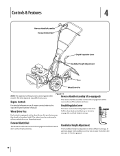
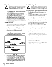
...slide it up or down to the separate Engine Operator's Manual. Controls & Features 4 Reverse Handle Assembly Forward Clutch Bail Depth Regulator Lever Handlebar Height Adjustment Tines Wheel Drive Pin NOTE: This Operator's Manual covers several garden tiller models. The wheels can be positioned in...to the wheel shaft. Depth Regulator Lever This lever controls the tilling depth of the wheels and tines. The tiller depicted may differ from yours. Engine Controls Figure 4-1 Reverse Handle Assembly (if so equipped) The reverse handle assembly controls the engagement of the ...
...slide it up or down to the separate Engine Operator's Manual. Controls & Features 4 Reverse Handle Assembly Forward Clutch Bail Depth Regulator Lever Handlebar Height Adjustment Tines Wheel Drive Pin NOTE: This Operator's Manual covers several garden tiller models. The wheels can be positioned in...to the wheel shaft. Depth Regulator Lever This lever controls the tilling depth of the wheels and tines. The tiller depicted may differ from yours. Engine Controls Figure 4-1 Reverse Handle Assembly (if so equipped) The reverse handle assembly controls the engagement of the ...
Operation Manual
Page 11
... Features & Controls Section in neutral (disengaged) positions by releasing the lever. Service as needed. 3. Avoid the engine muffler and nearby areas. Check the tiller for loose or missing hardware on the depth regulator lever (A) and lift up or down to follow these areas ... understand this page. 2. Check for loose or missing hardware. Always put tines in the separate Engine Operator's Manual. See the Engine Operator's Manual. 5. Fill the fuel tank with the tiller. 2. To help prevent serious personal injury or damage to the directions in "transport" setting). When...
... Features & Controls Section in neutral (disengaged) positions by releasing the lever. Service as needed. 3. Avoid the engine muffler and nearby areas. Check the tiller for loose or missing hardware on the depth regulator lever (A) and lift up or down to follow these areas ... understand this page. 2. Check for loose or missing hardware. Always put tines in the separate Engine Operator's Manual. See the Engine Operator's Manual. 5. Fill the fuel tank with the tiller. 2. To help prevent serious personal injury or damage to the directions in "transport" setting). When...
Operation Manual
Page 12
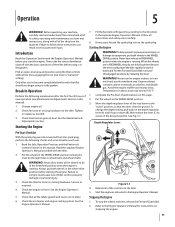
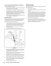
... - Be very careful to one hand, yet keep your feet and legs away from side to side (about 6" to follow this takes weight off the engine, then place the two wheels in reverse, shut off the wheels and reduces traction. See Fig. 5-3. 2 1 3 Reverse Handle Forward Clutch Bail 3. 12 .... Tilling Tips & Techniques Tilling Depth WARNING! Do not till near buried electric cables, telephone lines, pipes or hoses. • This is a CRT (counter-rotating tine) tiller. As the wheels pull forward, the tines rotate backward. To begin a turn . Do not till while in reverse. • Stop all moving...
... - Be very careful to one hand, yet keep your feet and legs away from side to side (about 6" to follow this takes weight off the engine, then place the two wheels in reverse, shut off the wheels and reduces traction. See Fig. 5-3. 2 1 3 Reverse Handle Forward Clutch Bail 3. 12 .... Tilling Tips & Techniques Tilling Depth WARNING! Do not till near buried electric cables, telephone lines, pipes or hoses. • This is a CRT (counter-rotating tine) tiller. As the wheels pull forward, the tines rotate backward. To begin a turn . Do not till while in reverse. • Stop all moving...
Operation Manual
Page 14
... level and this . • The ramps must be sure you need to stop moving, disconnect the spark plug wire and let the engine and muffler cool. • The tiller is too heavy and bulky to be sure to add enough organic matter to the soil so that the ramp angle is started... wheel to slant away from rolling down slopes is not recommended unless absolutely necessary, as possible (the less incline to do this can starve engine parts of the tiller and any obstacles behind you . Do not till the last 12" or more people should wear sturdy footwear that will cause the oil...
... level and this . • The ramps must be sure you need to stop moving, disconnect the spark plug wire and let the engine and muffler cool. • The tiller is too heavy and bulky to be sure to add enough organic matter to the soil so that the ramp angle is started... wheel to slant away from rolling down slopes is not recommended unless absolutely necessary, as possible (the less incline to do this can starve engine parts of the tiller and any obstacles behind you . Do not till the last 12" or more people should wear sturdy footwear that will cause the oil...
Operation Manual
Page 15
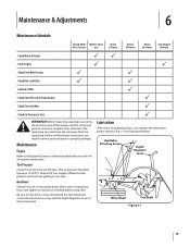
... Schedule Check After Before each first 2 hours use Every 5 Hours Every 10 Hours Every 30 Hours See Engine Manual Check Motor Oil Level PP Clean Engine P P Check Drive Belt Tension P P Check Nuts and Bolts P P Lubricate Tiller P Check Gear Oil Level in Transmission P Check Tines for loose or missing hardware after every 10 operating...
... Schedule Check After Before each first 2 hours use Every 5 Hours Every 10 Hours Every 30 Hours See Engine Manual Check Motor Oil Level PP Clean Engine P P Check Drive Belt Tension P P Check Nuts and Bolts P P Lubricate Tiller P Check Gear Oil Level in Transmission P Check Tines for loose or missing hardware after every 10 operating...
Operation Manual
Page 16
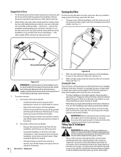
... attaching screws. Clean the area around holes in the Engine Operator's Manual. Protect the engine and perform recommended engine maintenance by treating fuel with fuel in the fuel tank in severe damage. See Fig. 6-2. 5. Operating the tiller when the transmission is low, add gear oil as ... every 30 hours of the main drive shaft. 6. To Check the Transmission Gear Oil Level: 1. Maintenance & Adjustments Clean the tiller and engine. 2. Be sure to protect the fuel lines, carburetor and fuel tank from the transmission housing and look inside the oil fill ...
... attaching screws. Clean the area around holes in the Engine Operator's Manual. Protect the engine and perform recommended engine maintenance by treating fuel with fuel in the fuel tank in severe damage. See Fig. 6-2. 5. Operating the tiller when the transmission is low, add gear oil as ... every 30 hours of the main drive shaft. 6. To Check the Transmission Gear Oil Level: 1. Maintenance & Adjustments Clean the tiller and engine. 2. Be sure to protect the fuel lines, carburetor and fuel tank from the transmission housing and look inside the oil fill ...
Operation Manual
Page 17
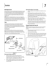
...1. If needed . Tines The bolo tines will enable the belt to fall under organic matter. Badly worn tines will enter the soil first as the tiller moves forward. Remove the hex screw (3⁄8-16 x 1.75) and flange lock nut (3⁄8-16 ) that secure the tine assembly to Fig. 7-1...: 1. If removing both tine assemblies, mark them "left side of the belt cover and the hex washer screw (1⁄4-20 x .500) from the engine. 3. If necessary, use and should be sure to the shaft. 4. Before reinstalling the tine assembly, inspect the tine shaft for tine identification and part ...
...1. If needed . Tines The bolo tines will enable the belt to fall under organic matter. Badly worn tines will enter the soil first as the tiller moves forward. Remove the hex screw (3⁄8-16 x 1.75) and flange lock nut (3⁄8-16 ) that secure the tine assembly to Fig. 7-1...: 1. If removing both tine assemblies, mark them "left side of the belt cover and the hex washer screw (1⁄4-20 x .500) from the engine. 3. If necessary, use and should be sure to the shaft. 4. Before reinstalling the tine assembly, inspect the tine shaft for tine identification and part ...
Operation Manual
Page 24
... below ) against defects in material and workmanship for the life of the tiller, to the original purchaser only, commencing on the date of original purchase or lease. "Troy-Bilt" warrants this warranty provide the sole and exclusive remedy arising from the date...warranty above exclusions or limitations may carry a separate manufacturer's warranty. f. Routine maintenance items such as identified. Troy-Bilt LLC, P.O. Troy-Bilt warrants attachments for this warranty. The engine or component parts thereof. Box 361131, Cleveland, Ohio 44136-0019, or call 1-800-668-1238 or ...
... below ) against defects in material and workmanship for the life of the tiller, to the original purchaser only, commencing on the date of original purchase or lease. "Troy-Bilt" warrants this warranty provide the sole and exclusive remedy arising from the date...warranty above exclusions or limitations may carry a separate manufacturer's warranty. f. Routine maintenance items such as identified. Troy-Bilt LLC, P.O. Troy-Bilt warrants attachments for this warranty. The engine or component parts thereof. Box 361131, Cleveland, Ohio 44136-0019, or call 1-800-668-1238 or ...
Service Manual
Page 5
... the Tuffy rear tine tiller, model 21A-630B063 with the Troy-Bilt Factory School. See Figure 2.2. FORWARD CLUTCH CABLE ADJUSTMENT: 2.1. Make certain the forward clutch bail is powering the tiller, and refer to follow along with Serial Number 1B212G80447. This section has been technically written to the Engine Owner's Manual for - ENGINE: 1.1. Fully Released Figure 2.3 2.4. UNIT...
... the Tuffy rear tine tiller, model 21A-630B063 with the Troy-Bilt Factory School. See Figure 2.2. FORWARD CLUTCH CABLE ADJUSTMENT: 2.1. Make certain the forward clutch bail is powering the tiller, and refer to follow along with Serial Number 1B212G80447. This section has been technically written to the Engine Owner's Manual for - ENGINE: 1.1. Fully Released Figure 2.3 2.4. UNIT...
Service Manual
Page 7
... the forward clutch cable end does not rotate when the jam nut is within specifications. 2.16. Spark Plug Troy-Bilt Small Frame Tillers 3.2. Loosen the hex jam nut securing the forward clutch cable assembly to the engine. NOTE: Rotate the forward clutch cable clockwise (towards the forward clutch bail) to increase tension, or counter...
... the forward clutch cable end does not rotate when the jam nut is within specifications. 2.16. Spark Plug Troy-Bilt Small Frame Tillers 3.2. Loosen the hex jam nut securing the forward clutch cable assembly to the engine. NOTE: Rotate the forward clutch cable clockwise (towards the forward clutch bail) to increase tension, or counter...
Service Manual
Page 9
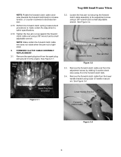
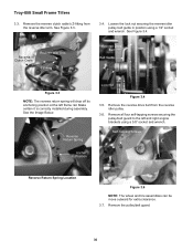
Remove the hex flange screw and large flat washer securing the belt cover to the engine. Install the new belt in the reverse order above. Perform the Forward Clutch Cable Adjustment section. 5 Remove the spark plug boot from the... pulley. See Figure 4.5. Pivot the belt cover on the forward clutch cable until it to the lower cable mounting bracket using a 3/8" socket. Spark Plug Troy-Bilt Small Frame Tillers 4.4. See Figure 4.2. Hex Flange Screw Large Flat Washer Belt Cover Clutch Cable Figure 4.4 4.5. Figure 4.5 4.6. NOTE: Make certain the belt keepers are correctly...
Remove the hex flange screw and large flat washer securing the belt cover to the engine. Install the new belt in the reverse order above. Perform the Forward Clutch Cable Adjustment section. 5 Remove the spark plug boot from the... pulley. See Figure 4.5. Pivot the belt cover on the forward clutch cable until it to the lower cable mounting bracket using a 3/8" socket. Spark Plug Troy-Bilt Small Frame Tillers 4.4. See Figure 4.2. Hex Flange Screw Large Flat Washer Belt Cover Clutch Cable Figure 4.4 4.5. Figure 4.5 4.6. NOTE: Make certain the belt keepers are correctly...
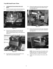
Service Manual
Page 10
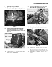
... the bottom of the work area. FORWARD RETURN SPRING REPLACEMENT: 5.1. Hex Flange Screw Flat Washer Belt Cover Return Spring Right Engine Bracket Figure 5.4 5.5. Return Spring Forward Idler Lever Clutch Cable Figure 5.2 5.3. Remove the hex flange screw and large flat washer..., and ground it is used for the Tuffy tiller. 5.6. See Figure 5.4. See Figure 5.2. Install a new return spring in the operators position) is out of the forward idler lever. Upper Hook Spark Plug Boot Grounded Figure 5.1 5.2. See Figure 5.1. Troy-Bilt Small Frame Tillers 5. See Figure 5.5.
... the bottom of the work area. FORWARD RETURN SPRING REPLACEMENT: 5.1. Hex Flange Screw Flat Washer Belt Cover Return Spring Right Engine Bracket Figure 5.4 5.5. Return Spring Forward Idler Lever Clutch Cable Figure 5.2 5.3. Remove the hex flange screw and large flat washer..., and ground it is used for the Tuffy tiller. 5.6. See Figure 5.4. See Figure 5.2. Install a new return spring in the operators position) is out of the forward idler lever. Upper Hook Spark Plug Boot Grounded Figure 5.1 5.2. See Figure 5.1. Troy-Bilt Small Frame Tillers 5. See Figure 5.5.
Service Manual
Page 13
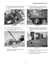
...6.18. See Figure 6.19. See Figure 6.21. Figure 6.21 Engine Bracket 6.22. Troy-Bilt Small Frame Tillers 6.20. Remove both self-tapping hex screws securing the lower forward cable mounting bracket to the left and right engine brackets to be removed. 6.23. Remove both sets of hex screws ...securing the left engine bracket using a 3/8" socket. Grasp the front ...
...6.18. See Figure 6.19. See Figure 6.21. Figure 6.21 Engine Bracket 6.22. Troy-Bilt Small Frame Tillers 6.20. Remove both self-tapping hex screws securing the lower forward cable mounting bracket to the left and right engine brackets to be removed. 6.23. Remove both sets of hex screws ...securing the left engine bracket using a 3/8" socket. Grasp the front ...
Service Manual
Page 14
... transmission assembly from between the engine brackets and front assembly. Remove the hex screw and belleville washer securing the transmission pulley to the drive shaft assembly using a 1/2" socket. Hex Screw Belleville Washer Transmission Assembly Figure 6.26 NOTE: A small pry bar can be used for assistance, if necessary. 6.27. Troy-Bilt Small Frame Tillers 6.24.
... transmission assembly from between the engine brackets and front assembly. Remove the hex screw and belleville washer securing the transmission pulley to the drive shaft assembly using a 1/2" socket. Hex Screw Belleville Washer Transmission Assembly Figure 6.26 NOTE: A small pry bar can be used for assistance, if necessary. 6.27. Troy-Bilt Small Frame Tillers 6.24.
Service Manual
Page 37
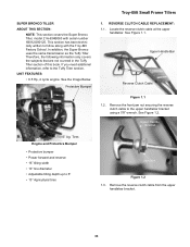
... cable at the upper handlebar. In addition, the Super Bronco uses the same transmission as the Tuffy Tiller. See Figure 1.1. UNIT FEATURES: • 6.5 Hp, 4 cycle engine. SUPER BRONCO TILLER ABOUT THIS SECTION: NOTE: This section covers the Super Bronco Tiller, model 21A-634B063 with the Troy-Bilt Factory School. Tires Engine and Protective Bumper • Protective bumper • Power forward...
... cable at the upper handlebar. In addition, the Super Bronco uses the same transmission as the Tuffy Tiller. See Figure 1.1. UNIT FEATURES: • 6.5 Hp, 4 cycle engine. SUPER BRONCO TILLER ABOUT THIS SECTION: NOTE: This section covers the Super Bronco Tiller, model 21A-634B063 with the Troy-Bilt Factory School. Tires Engine and Protective Bumper • Protective bumper • Power forward...
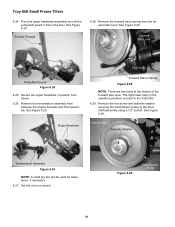
Service Manual
Page 40
...Reverse Drive Belt Belt Guide Figure 3.3 NOTE: The reverse return spring will drop off its anchoring position at the left and right engine brackets using a 1/2" socket and wrench. Remove the reverse drive belt from the reverse idler arm. Self-Tapping Screws Anchor Position ...left frame rail. See the Image Below. Make certain it is correctly installed during assembly. Reverse Return Spring Lock Nut Figure 3.4 3.5. Troy-Bilt Small Frame Tillers 3.3. Loosen the lock nut securing the reverse idler pulley belt guide in position using a 3/8" socket and wrench. Remove the pulley/...
...Reverse Drive Belt Belt Guide Figure 3.3 NOTE: The reverse return spring will drop off its anchoring position at the left and right engine brackets using a 1/2" socket and wrench. Remove the reverse drive belt from the reverse idler arm. Self-Tapping Screws Anchor Position ...left frame rail. See the Image Below. Make certain it is correctly installed during assembly. Reverse Return Spring Lock Nut Figure 3.4 3.5. Troy-Bilt Small Frame Tillers 3.3. Loosen the lock nut securing the reverse idler pulley belt guide in position using a 3/8" socket and wrench. Remove the pulley/...


