
Product Specification
Page 15
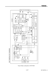
XM-7002B Rev.1.0 Figure 5 Basic configuration of XM-7002B 11/27 XM-7002B BLOCK DIAGRAM D ISC MOTOR PUH MO DRIVER EJECT SW FEED MOTOR POSITION DETECTOR DRAWER RELEASE DETECTOR B USY LED SOLENOID EJECT MUTING RF AMP SERVO AMP Eject TRACKING F OCUS Feed-Mo EFM ... DAC EFFECT RAM VCO 17/34 MHz ERROR CORRECTION SERVO CONTROL MASTER CLOCK GEN. 33.86 MHz D-RAM 128 kB CD-ROM DATA SYNC DETECT CONTROL DE-SCRAMBLE HEADER DETECT ERROR CORRECTION IDE/ATAPI INTERFACE CONTROL 50 MHz + 5 V GND FN CONV. ACCESS CONTROL PERIPHERAL INTERFACE TIMING CONTROL TIMER INT.CONTROL RAM 2 kB...
XM-7002B Rev.1.0 Figure 5 Basic configuration of XM-7002B 11/27 XM-7002B BLOCK DIAGRAM D ISC MOTOR PUH MO DRIVER EJECT SW FEED MOTOR POSITION DETECTOR DRAWER RELEASE DETECTOR B USY LED SOLENOID EJECT MUTING RF AMP SERVO AMP Eject TRACKING F OCUS Feed-Mo EFM ... DAC EFFECT RAM VCO 17/34 MHz ERROR CORRECTION SERVO CONTROL MASTER CLOCK GEN. 33.86 MHz D-RAM 128 kB CD-ROM DATA SYNC DETECT CONTROL DE-SCRAMBLE HEADER DETECT ERROR CORRECTION IDE/ATAPI INTERFACE CONTROL 50 MHz + 5 V GND FN CONV. ACCESS CONTROL PERIPHERAL INTERFACE TIMING CONTROL TIMER INT.CONTROL RAM 2 kB...
Product Specification
Page 17
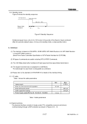
... by command. (5) Please refer to 10X mode in 8 seconds of single ended TTL compatible receivers and drivers communicating through a 50P-conductor as shown in Figure 9,10 - 13. 13/27 XM-7002B Rev.1.0 Standby mode Figure 8 shows the standby sequence. During access ldle (Max.24X) ldle (4.4 ...6. Interface (1) The interface is 2,448 Bytes. 5.3. After 24 seconds (default value), it move onto 4.4 to the standard of ATA/ATAPI-4 for CD-ROMs) (2) 48 types of commands are usable including ATA & ATAPI Commands. (3) The 128 KByte data buffer handles both high speed and low speed data ...
... by command. (5) Please refer to 10X mode in 8 seconds of single ended TTL compatible receivers and drivers communicating through a 50P-conductor as shown in Figure 9,10 - 13. 13/27 XM-7002B Rev.1.0 Standby mode Figure 8 shows the standby sequence. During access ldle (Max.24X) ldle (4.4 ...6. Interface (1) The interface is 2,448 Bytes. 5.3. After 24 seconds (default value), it move onto 4.4 to the standard of ATA/ATAPI-4 for CD-ROMs) (2) 48 types of commands are usable including ATA & ATAPI Commands. (3) The 128 KByte data buffer handles both high speed and low speed data ...
Product Specification
Page 21
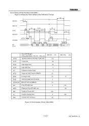
... (ns) 120 55 34 6 0 20 20 0 20 0 100 0 20 Figure 12 Host Interface Timing (Ultra DMA) Max time (ns) 70 170 50 150 17/27 XM-7002B Rev.1.0 6.2.4.Timing of Host Interface (Ultra DMA ) Figure 12 shows the Host Interface Ultra DMA word Timings tMLI DMARQ tUI DMACKSTOP DMARDY STROBE DD (15... Setup time tDVH Data Hold time tUI Unlimited Interlock time tACK Setup and Hold Time for DMACK- tENV Envelope time t2AD Minimum Delay time for Driver t2IORODY Minimum time for DMACK-
... (ns) 120 55 34 6 0 20 20 0 20 0 100 0 20 Figure 12 Host Interface Timing (Ultra DMA) Max time (ns) 70 170 50 150 17/27 XM-7002B Rev.1.0 6.2.4.Timing of Host Interface (Ultra DMA ) Figure 12 shows the Host Interface Ultra DMA word Timings tMLI DMARQ tUI DMACKSTOP DMARDY STROBE DD (15... Setup time tDVH Data Hold time tUI Unlimited Interlock time tACK Setup and Hold Time for DMACK- tENV Envelope time t2AD Minimum Delay time for Driver t2IORODY Minimum time for DMACK-