
User Manual
Page 27
... panel 52 Your computer's features and specifications ....53 Turning on the power 53 Adding memory (optional 55 Installing a memory module 55 Removing a memory module 60 Hard Drive Recovery Utilities 63 Creating Recovery CDs/DVDs 64 Hard Disk Drive Recovery using the recovery partition 65 Hard...devices 78 Directing the display output when you turn on the computer 78 Adjusting the quality of the external display......80 Using an external keyboard 80 Using a mouse 80 Connecting a printer 81 Setting up a printer 82 Connecting an optional external diskette drive........83 Turning off ...
... panel 52 Your computer's features and specifications ....53 Turning on the power 53 Adding memory (optional 55 Installing a memory module 55 Removing a memory module 60 Hard Drive Recovery Utilities 63 Creating Recovery CDs/DVDs 64 Hard Disk Drive Recovery using the recovery partition 65 Hard...devices 78 Directing the display output when you turn on the computer 78 Adjusting the quality of the external display......80 Using an external keyboard 80 Using a mouse 80 Connecting a printer 81 Setting up a printer 82 Connecting an optional external diskette drive........83 Turning off ...
User Manual
Page 28
... 93 Moving the computer 93 Using a computer lock 94 Chapter 2: Learning the Basics 95 Computing tips 95 Using the keyboard 97 Character keys 97 Making your keyboard emulate a full-size keyboard 97 Ctrl, Fn, and Alt keys 98 Function keys 98 Windows special keys 99 Overlay keys 99 Using the overlay ...Using the optical drive 107 Optical drive components 108 Inserting a compact disc 109 Playing an audio CD 111 Playing CDs 112 Creating a CD 113 Removing a disc with the computer on...........114 Removing a disc with the computer off ..........114 Caring for CD or DVD Discs 115...
... 93 Moving the computer 93 Using a computer lock 94 Chapter 2: Learning the Basics 95 Computing tips 95 Using the keyboard 97 Character keys 97 Making your keyboard emulate a full-size keyboard 97 Ctrl, Fn, and Alt keys 98 Function keys 98 Windows special keys 99 Overlay keys 99 Using the overlay ...Using the optical drive 107 Optical drive components 108 Inserting a compact disc 109 Playing an audio CD 111 Playing CDs 112 Creating a CD 113 Removing a disc with the computer on...........114 Removing a disc with the computer off ..........114 Caring for CD or DVD Discs 115...

User Manual
Page 31
...assign a key 172 Using the keyboard or pointing device to assign a key 173 Viewing existing key assignments 174 Changing or removing existing key assignments 175 Toshiba Hotkey Utility 175 Toshiba SD™ Memory Card Format Utility............176 Toshiba SD™ Memory Boot Utility ...177 Booting from a bootable SD card 178 Toshiba Power Saver 179 Preset Power Profiles ...
...assign a key 172 Using the keyboard or pointing device to assign a key 173 Viewing existing key assignments 174 Changing or removing existing key assignments 175 Toshiba Hotkey Utility 175 Toshiba SD™ Memory Card Format Utility............176 Toshiba SD™ Memory Boot Utility ...177 Booting from a bootable SD card 178 Toshiba Power Saver 179 Preset Power Profiles ...
User Manual
Page 47
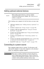
...optional external devices 47 Adding optional external devices NOTE Before adding external devices or memory, Toshiba recommends setting up your software" on page 45. Failure to follow this instruction may ...10070; Connect a mouse (see "Using a mouse" on page 80) ❖ Connect a full-size keyboard (see "Using an external keyboard" on page 80) ❖ Connect an external monitor (see "Using external display devices" on page ... ❖ Install PC Cards (see "Using PC Cards" on a power cord/cable to remove a plug from a socket. Never pull on page 150) Connecting to a power source Your ...
...optional external devices 47 Adding optional external devices NOTE Before adding external devices or memory, Toshiba recommends setting up your software" on page 45. Failure to follow this instruction may ...10070; Connect a mouse (see "Using a mouse" on page 80) ❖ Connect a full-size keyboard (see "Using an external keyboard" on page 80) ❖ Connect an external monitor (see "Using external display devices" on page ... ❖ Install PC Cards (see "Using PC Cards" on a power cord/cable to remove a plug from a socket. Never pull on page 150) Connecting to a power source Your ...
User Manual
Page 122
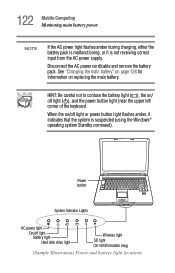
... remove the battery pack. When the on / off light or power button light flashes amber, it is suspended (using the Windows® operating system Standby command). HINT: Be careful not to confuse the battery light ( ), the on /off light ( ), and the power button light (near the upper left corner of the keyboard...
... remove the battery pack. When the on / off light or power button light flashes amber, it is suspended (using the Windows® operating system Standby command). HINT: Be careful not to confuse the battery light ( ), the on /off light ( ), and the power button light (near the upper left corner of the keyboard...

User Manual
Page 175
To activate the Hotkey utility: 1 Click Start, All Programs, Toshiba, Utilities, Hotkey utility. Toshiba Hotkey Utility The Toshiba Hotkey utility allows you to change the key assignment, click Direct or Popup and continue as if you use the Hotkey ...[Fn+F4]. Fn-esse displays the Assignment Type dialog box. ❖ To change with the secondary button. 175 Toshiba Utilities Toshiba Hotkey Utility Changing or removing existing key assignments On the Fn-esse keyboard, click the key you wish to receive a confirmation message when you were creating a new assignment. ❖ To...
To activate the Hotkey utility: 1 Click Start, All Programs, Toshiba, Utilities, Hotkey utility. Toshiba Hotkey Utility The Toshiba Hotkey utility allows you to change the key assignment, click Direct or Popup and continue as if you use the Hotkey ...[Fn+F4]. Fn-esse displays the Assignment Type dialog box. ❖ To change with the secondary button. 175 Toshiba Utilities Toshiba Hotkey Utility Changing or removing existing key assignments On the Fn-esse keyboard, click the key you wish to receive a confirmation message when you were creating a new assignment. ❖ To...
User Manual
Page 293
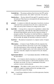
...more information than diskettes and are connected. A feature of many Toshiba notebook computers that holds 1.44 MB of reference for long-term storage of a computer system. A 3.5-inch diskette that saves to add or remove devices from a computer while the computer is determined by the...you turn the computer off . A small image displayed on the keyboard. hot swapping - 293 Glossary frontside bus - See also bus. The keys labeled F1 through F12, typically located on the screen that are removable. Compare software. See also Standby, Suspend. By default, the hard...
...more information than diskettes and are connected. A feature of many Toshiba notebook computers that holds 1.44 MB of reference for long-term storage of a computer system. A 3.5-inch diskette that saves to add or remove devices from a computer while the computer is determined by the...you turn the computer off . A small image displayed on the keyboard. hot swapping - 293 Glossary frontside bus - See also bus. The keys labeled F1 through F12, typically located on the screen that are removable. Compare software. See also Standby, Suspend. By default, the hard...

User Manual
Page 301
301 Index communications network connection 142 system resources 213 compact disc positioning 110 compact discs handling 111 inserting 109 removing 114 computer non-system disk or disk error message 209 not accessing disk drives 208 running on battery power 116 setting up...desktop creating new icon 136 major features 136 desktop exploration 135 desktop icons 136 Device Manager 214 checking properties 215 disabling a device 215 devices keyboard 80 mouse 80 Disk Defragmenter 223 disk drive corrupted/damaged data files 224 missing files/trouble accessing a disk 222 running slow 223 diskette drive...
301 Index communications network connection 142 system resources 213 compact disc positioning 110 compact discs handling 111 inserting 109 removing 114 computer non-system disk or disk error message 209 not accessing disk drives 208 running on battery power 116 setting up...desktop creating new icon 136 major features 136 desktop exploration 135 desktop icons 136 Device Manager 214 checking properties 215 disabling a device 215 devices keyboard 80 mouse 80 Disk Defragmenter 223 disk drive corrupted/damaged data files 224 missing files/trouble accessing a disk 222 running slow 223 diskette drive...

User Manual
Page 302
..., backing up 96 files backing up 106 printing 105 restoring 107 saving 103 fingerprint authentication 192 enrollment 192 FN keys 98 Fn-esse change/remove key assignments 175 starting 171 Fn-esse program 171 assigning a key 171 using drag-and-drop 172 function keys 98 H hardware conflicts 212...Hibernation mode 85 configuring 89 starting again from 91 hot key display brightness 257 display modes 256 Hibernation mode 255 instant password security 251 keyboard 258 keyboard overlays 257, 259 password security 251 power usage mode 253 Standby mode 254 volume mute 250 hot key power usage mode 127 hot...
..., backing up 96 files backing up 106 printing 105 restoring 107 saving 103 fingerprint authentication 192 enrollment 192 FN keys 98 Fn-esse change/remove key assignments 175 starting 171 Fn-esse program 171 assigning a key 171 using drag-and-drop 172 function keys 98 H hardware conflicts 212...Hibernation mode 85 configuring 89 starting again from 91 hot key display brightness 257 display modes 256 Hibernation mode 255 instant password security 251 keyboard 258 keyboard overlays 257, 259 password security 251 power usage mode 253 Standby mode 254 volume mute 250 hot key power usage mode 127 hot...

User Manual
Page 303
...145 IRQ (Interrupt Request) 213 ISPs 145 J jack RJ-11 141 K key changing 175 removing 175 key assignment viewing existing 174 key assignments changing or removing existing 175 keyboard character keys 97 function keys 98 hot keys 257, 259 not working 208 overlay keys 99 ...troubleshooting 219 Windows special keys 99 keyboard, external 80 keyboard, PS/2-compatible 80 M main battery removing 128 memory adding 55 problem solving 216 removing expansion slot cover 57 memory module installation 55 installing inserting into socket 58 removing 61 microphone 148 modem determining COM port ...
...145 IRQ (Interrupt Request) 213 ISPs 145 J jack RJ-11 141 K key changing 175 removing 175 key assignment viewing existing 174 key assignments changing or removing existing 175 keyboard character keys 97 function keys 98 hot keys 257, 259 not working 208 overlay keys 99 ...troubleshooting 219 Windows special keys 99 keyboard, external 80 keyboard, PS/2-compatible 80 M main battery removing 128 memory adding 55 problem solving 216 removing expansion slot cover 57 memory module installation 55 installing inserting into socket 58 removing 61 microphone 148 modem determining COM port ...

User Manual
Page 304
... swapping fails 229 inserting 151 modem default 139 not recognized 229 problem solving 226, 228 removing 151 setting up 152 Plug and Play 213 port COM 139 Ethernet LAN 142 RGB 78...device properties 215 computer hangs when PC Card inserted 228 computer will not power up 207 contacting Toshiba 245, 246 corrupted/damaged data files 224 Device Manager 214 disabling a device 215 disk drive... noise 226 illegal operation 206 Internet bookmarked site not found 211 Internet connection is slow 211 keyboard not responding 208 missing files/trouble accessing a disk 222 modem not receiving or transmitting 231 ...
... swapping fails 229 inserting 151 modem default 139 not recognized 229 problem solving 226, 228 removing 151 setting up 152 Plug and Play 213 port COM 139 Ethernet LAN 142 RGB 78...device properties 215 computer hangs when PC Card inserted 228 computer will not power up 207 contacting Toshiba 245, 246 corrupted/damaged data files 224 Device Manager 214 disabling a device 215 disk drive... noise 226 illegal operation 206 Internet bookmarked site not found 211 Internet connection is slow 211 keyboard not responding 208 missing files/trouble accessing a disk 222 modem not receiving or transmitting 231 ...
Maintenance Manual
Page 4
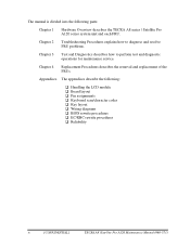
Appendices The appendices describe the following parts: Chapter 1 Hardware Overview describes the TECRA A8 series / Satellite Pro A120 series system unit and each FRU. Chapter 2 Troubleshooting Procedures explains how to diagnose and ...layout ‰ Pin assignments ‰ Keyboard scan/character codes ‰ Key layout ‰ Wiring diagrams ‰ BIOS rewrite procedures ‰ EC/KBC rewrite procedures ‰ Reliability iv [CONFIDENTIAL] TECRA A8 /Satellite Pro A120 Maintenance Manual (960-573) Chapter 4 Replacement Procedures describes the removal and replacement of the FRUs.
Appendices The appendices describe the following parts: Chapter 1 Hardware Overview describes the TECRA A8 series / Satellite Pro A120 series system unit and each FRU. Chapter 2 Troubleshooting Procedures explains how to diagnose and ...layout ‰ Pin assignments ‰ Keyboard scan/character codes ‰ Key layout ‰ Wiring diagrams ‰ BIOS rewrite procedures ‰ EC/KBC rewrite procedures ‰ Reliability iv [CONFIDENTIAL] TECRA A8 /Satellite Pro A120 Maintenance Manual (960-573) Chapter 4 Replacement Procedures describes the removal and replacement of the FRUs.

Maintenance Manual
Page 244
... assembly (2 4-28 Removing the cover assembly (3 4-29 Removing the switch cover 4-31 Removing the SW membrane 4-32 Removing the fingerprint sensor board 4-33 Removing the touch pad (1 4-35 Removing the touch pad (2 4-36 Removing the SD card slot 4-38 Removing the Bluetooth module 4-39 Removing the serial/s-video board 4-41 Removing the RTC battery 4-43 4-iv [CONFIDENTIAL] TECRA A8 /Satellite Pro A120...
... assembly (2 4-28 Removing the cover assembly (3 4-29 Removing the switch cover 4-31 Removing the SW membrane 4-32 Removing the fingerprint sensor board 4-33 Removing the touch pad (1 4-35 Removing the touch pad (2 4-36 Removing the SD card slot 4-38 Removing the Bluetooth module 4-39 Removing the serial/s-video board 4-41 Removing the RTC battery 4-43 4-iv [CONFIDENTIAL] TECRA A8 /Satellite Pro A120...

Maintenance Manual
Page 265
... releasing the hook and turn the keyboard face down on either side and remove the keyboard holder. 4. Remove the following screws securing the keyboard. • M2.5×4B FLAT HEAD screw ×2 5. Keyboard holder Slit M2.5×4B FLAT HEAD Slit M2.5×4B FLAT HEAD Keyboard Hook Figure 4-10 Removing the keyboard (1) TECRA A8 /Satellite Pro A120 Maintenance Manual (960...
... releasing the hook and turn the keyboard face down on either side and remove the keyboard holder. 4. Remove the following screws securing the keyboard. • M2.5×4B FLAT HEAD screw ×2 5. Keyboard holder Slit M2.5×4B FLAT HEAD Slit M2.5×4B FLAT HEAD Keyboard Hook Figure 4-10 Removing the keyboard (1) TECRA A8 /Satellite Pro A120 Maintenance Manual (960...

Maintenance Manual
Page 266
Disconnect the keyboard cable from the connector CN3230 on the system board and remove the keyboard. 4 Replacement Procedures 4.7 Keyboard 6. Remove the following screw and keyboard support plate. • M2.5×6B FLAT HEAD screw ×1 7. M2.5×6B FLAT HEAD Keyboard support plate Keyboard cable CN3230 Keyboard Figure 4-11 Removing the keyboard (2) 4-20 [CONFIDENTIAL] TECRA A8 /Satellite Pro A120 Maintenance Manual (960-573)
Disconnect the keyboard cable from the connector CN3230 on the system board and remove the keyboard. 4 Replacement Procedures 4.7 Keyboard 6. Remove the following screw and keyboard support plate. • M2.5×6B FLAT HEAD screw ×1 7. M2.5×6B FLAT HEAD Keyboard support plate Keyboard cable CN3230 Keyboard Figure 4-11 Removing the keyboard (2) 4-20 [CONFIDENTIAL] TECRA A8 /Satellite Pro A120 Maintenance Manual (960-573)
Maintenance Manual
Page 303
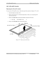
... HEAD LCD mask Figure 4-37 Removing the LCD mask TECRA A8 /Satellite Pro A120 Maintenance Manual (960-573) [CONFIDENTIAL] 4-57 4.25 LCD unit/FL inverter 4 Replacement Procedures 4 Replacement Procedures 4.25 LCD unit/FL inverter Removing the LCD unit/FL inverter To remove the LCD unit/FL inverter, ...Figure 4-37 to 4-40. 1. Remove the mask seals and following screws securing the LCD mask. • M2.5×6B FLAT HEAD screw ×2 4. Open the display and make it flat. 2. Remove the LCD mask while releasing the latches. Remove the keyboard cover while releasing latches. (In the...
... HEAD LCD mask Figure 4-37 Removing the LCD mask TECRA A8 /Satellite Pro A120 Maintenance Manual (960-573) [CONFIDENTIAL] 4-57 4.25 LCD unit/FL inverter 4 Replacement Procedures 4 Replacement Procedures 4.25 LCD unit/FL inverter Removing the LCD unit/FL inverter To remove the LCD unit/FL inverter, ...Figure 4-37 to 4-40. 1. Remove the mask seals and following screws securing the LCD mask. • M2.5×6B FLAT HEAD screw ×2 4. Open the display and make it flat. 2. Remove the LCD mask while releasing the latches. Remove the keyboard cover while releasing latches. (In the...
Maintenance Manual
Page 423
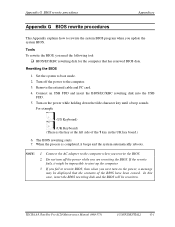
...you next turn off the power to boot mode. 2. TECRA A8 /Satellite Pro A120 Maintenance Manual (960-573) [CONFIDENTIAL] G-1 Connect an USB FDD and insert the BIOS/EC/KBC rewriting disk into the USB FDD. 5. For example (US Keyboard) (UK Keyboard) (There is completed, it might be impossible to start ...up the computer. 3 If you fail to the computer when you update the system BIOS. Remove the external cable and PC card. 4. In this case, insert ...
...you next turn off the power to boot mode. 2. TECRA A8 /Satellite Pro A120 Maintenance Manual (960-573) [CONFIDENTIAL] G-1 Connect an USB FDD and insert the BIOS/EC/KBC rewriting disk into the USB FDD. 5. For example (US Keyboard) (UK Keyboard) (There is completed, it might be impossible to start ...up the computer. 3 If you fail to the computer when you update the system BIOS. Remove the external cable and PC card. 4. In this case, insert ...


