

Service Manual
Page 2
... SPECIFICATION 9 2.1.1 HARDWARE 9 2.1.2 SOFTWARE 10 2.1.3 PHYSICAL 11 2.1.4 VIDEO 12 2.1.5 OTHERS 13 2.1.6 PRODUCT OVERVIEW 15 2.2 INTERFACES 16 2.2.1 SIM CARD INTERFACE 16 2.2.2 MEMORY CARD INTERFACE 18 2.2.3 BATTERY INTERFACE 20 2.2.4 CHARGING THE BATTERY 21 2.2.5 CHARGING INDICATOR 22 2.3 HANDSET USER INTERFACE 23 2.3.1 HANDSET DESCRIPTION 23 2.3.2 KEY FUNCTIONS 24 2.3.3 DISPLAY CONCEPT 26 2.3.4 MAIN MENU 27 2.4 MMI TEST 29...
... SPECIFICATION 9 2.1.1 HARDWARE 9 2.1.2 SOFTWARE 10 2.1.3 PHYSICAL 11 2.1.4 VIDEO 12 2.1.5 OTHERS 13 2.1.6 PRODUCT OVERVIEW 15 2.2 INTERFACES 16 2.2.1 SIM CARD INTERFACE 16 2.2.2 MEMORY CARD INTERFACE 18 2.2.3 BATTERY INTERFACE 20 2.2.4 CHARGING THE BATTERY 21 2.2.5 CHARGING INDICATOR 22 2.3 HANDSET USER INTERFACE 23 2.3.1 HANDSET DESCRIPTION 23 2.3.2 KEY FUNCTIONS 24 2.3.3 DISPLAY CONCEPT 26 2.3.4 MAIN MENU 27 2.4 MMI TEST 29...
Service Manual
Page 7
A mobile handset contains many parts such as batteries, chargers, multimedia cards and sim cards can be replaced in normal conditions (Non ESD protected environment). 3- Should you require any transportation of 103 These parts, ... information on ESD please refer to ESD. 4- MOBILE COMMUNICATIONS DIVISION CUSTOMER SERVICES 1.2 ESD (Electro Static Discharge)PROTECTION SERVICE REQUIRMENTS 1- Accessories such as LCD's and cameras. Toshiba require that all TPSV's ensure that the technicians work bench has sufficient ESD protection. 2-
A mobile handset contains many parts such as batteries, chargers, multimedia cards and sim cards can be replaced in normal conditions (Non ESD protected environment). 3- Should you require any transportation of 103 These parts, ... information on ESD please refer to ESD. 4- MOBILE COMMUNICATIONS DIVISION CUSTOMER SERVICES 1.2 ESD (Electro Static Discharge)PROTECTION SERVICE REQUIRMENTS 1- Accessories such as LCD's and cameras. Toshiba require that all TPSV's ensure that the technicians work bench has sufficient ESD protection. 2-
Service Manual
Page 12
... Playback Dvix Support Audio Codec Features Audio Chip Audio Encode Capability Audio Decode Capability FM Recording Melody Support Interface MP3 MP3 ring tone Battery standby time Battery Voice talk time Battery Capacity Description Remark X8 BMP, JPEG, GIF, PNG CIF @ 15fps N/A CIF @ 15fps N/A N/A N/A N/A N/A N/A N/A N/A N/A Wolfson WM8976 AMR AMR/MP3(H/W)/AAC+ N/A Poly40 (TBD) I2S (MP3...
... Playback Dvix Support Audio Codec Features Audio Chip Audio Encode Capability Audio Decode Capability FM Recording Melody Support Interface MP3 MP3 ring tone Battery standby time Battery Voice talk time Battery Capacity Description Remark X8 BMP, JPEG, GIF, PNG CIF @ 15fps N/A CIF @ 15fps N/A N/A N/A N/A N/A N/A N/A N/A N/A Wolfson WM8976 AMR AMR/MP3(H/W)/AAC+ N/A Poly40 (TBD) I2S (MP3...
Service Manual
Page 16
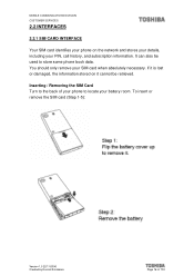
... retrieved. To insert or remove the SIM card (Step 1-5): Version 1.0 22/11/2006 Created by Konrad Szombara Page 16 of your phone to locate your battery room. MOBILE COMMUNICATIONS DIVISION CUSTOMER SERVICES 2.2 INTERFACES 2.2.1 SIM CARD INTERFACE Your SIM card identifies your phone on it cannot be used to the back of...
... retrieved. To insert or remove the SIM card (Step 1-5): Version 1.0 22/11/2006 Created by Konrad Szombara Page 16 of your phone to locate your battery room. MOBILE COMMUNICATIONS DIVISION CUSTOMER SERVICES 2.2 INTERFACES 2.2.1 SIM CARD INTERFACE Your SIM card identifies your phone on it cannot be used to the back of...

Service Manual
Page 18
The battery cover is located under the battery. To insert or remove the Memory card (Step 1-5): Version 1.0 22/11/2006 Created by Konrad Szombara Page 18 of your battery room. The memory card slot is located on the rear of the phone. Inserting / Removing the Memory slot Turn to the back of 103 MOBILE COMMUNICATIONS DIVISION CUSTOMER SERVICES 2.2.2 MEMORY CARD INTERFACE Your Phones supports a microSD card up to locate your phone to 1GB.
The battery cover is located under the battery. To insert or remove the Memory card (Step 1-5): Version 1.0 22/11/2006 Created by Konrad Szombara Page 18 of your battery room. The memory card slot is located on the rear of the phone. Inserting / Removing the Memory slot Turn to the back of 103 MOBILE COMMUNICATIONS DIVISION CUSTOMER SERVICES 2.2.2 MEMORY CARD INTERFACE Your Phones supports a microSD card up to locate your phone to 1GB.
Service Manual
Page 20
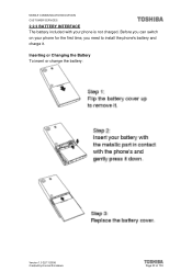
MOBILE COMMUNICATIONS DIVISION CUSTOMER SERVICES 2.2.3 BATTERY INTERFACE The battery included with your phone for the first time, you need to install the phone's battery and charge it. Before you can switch on your phone is not charged. Inserting or Changing the Battery To insert or change the battery: Version 1.0 22/11/2006 Created by Konrad Szombara Page 20 of 103
MOBILE COMMUNICATIONS DIVISION CUSTOMER SERVICES 2.2.3 BATTERY INTERFACE The battery included with your phone for the first time, you need to install the phone's battery and charge it. Before you can switch on your phone is not charged. Inserting or Changing the Battery To insert or change the battery: Version 1.0 22/11/2006 Created by Konrad Szombara Page 20 of 103
Service Manual
Page 21
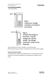
You should disconnect the charger from the power outlet before you disconnect the charger. Version 1.0 22/11/2006 Created by Konrad Szombara Page 21 of 103 Disconnecting the charger To disconnect the charger, grip it tightly and pull. MOBILE COMMUNICATIONS DIVISION CUSTOMER SERVICES 2.2.4 Charging the Battery To charge a battery: During charging, there will no indication on the phone screen. Please keep the phone charge for a white before disconnecting the charger from the phone.
You should disconnect the charger from the power outlet before you disconnect the charger. Version 1.0 22/11/2006 Created by Konrad Szombara Page 21 of 103 Disconnecting the charger To disconnect the charger, grip it tightly and pull. MOBILE COMMUNICATIONS DIVISION CUSTOMER SERVICES 2.2.4 Charging the Battery To charge a battery: During charging, there will no indication on the phone screen. Please keep the phone charge for a white before disconnecting the charger from the phone.
Service Manual
Page 22
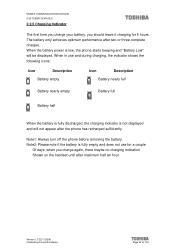
... handset until after maximum half an hour. Version 1.0 22/11/2006 Created by Konrad Szombara Page 22 of 103 The battery only achieves optimum performance after the phone has recharged sufficiently. When in use for 8 hours. Note1: Always turn off the ...charging, the indicator shows the following icons: Icon Description Battery empty Icon Description Battery nearly full Battery nearly empty Battery full Battery half When the battery is fully discharged, the charging indicator is low, the phone starts beeping and "Battery Low" will not appear after two or three complete ...
... handset until after maximum half an hour. Version 1.0 22/11/2006 Created by Konrad Szombara Page 22 of 103 The battery only achieves optimum performance after the phone has recharged sufficiently. When in use for 8 hours. Note1: Always turn off the ...charging, the indicator shows the following icons: Icon Description Battery empty Icon Description Battery nearly full Battery nearly empty Battery full Battery half When the battery is fully discharged, the charging indicator is low, the phone starts beeping and "Battery Low" will not appear after two or three complete ...

Service Manual
Page 26
MOBILE COMMUNICATIONS DIVISION CUSTOMER SERVICES 2.3.3 Display Concept - Icon 1 2 3 4 5 6 7 8 9 10 Version 1.0 22/11/2006 Created by Konrad Szombara Description Signal Strength (lower to high) Roaming Keypad lock Appointments Bluetooth (active/connecting) Phone set to mute/Vibrate Alarm Set Message indicator Battery level ( empty to full) Headset Page 26 of 103 Main No.
MOBILE COMMUNICATIONS DIVISION CUSTOMER SERVICES 2.3.3 Display Concept - Icon 1 2 3 4 5 6 7 8 9 10 Version 1.0 22/11/2006 Created by Konrad Szombara Description Signal Strength (lower to high) Roaming Keypad lock Appointments Bluetooth (active/connecting) Phone set to mute/Vibrate Alarm Set Message indicator Battery level ( empty to full) Headset Page 26 of 103 Main No.

Service Manual
Page 33
... 1.2 ANTENNA FPC Part Number TBD 33VI5TC0I01 DQ663196502 2 BASE CASE ASSY VI5 SILVER 3 MIDDLE CASE ASSY VI5 4 RECEIVER (SPK 320OHM) 5 SPEAKER 8 OHM 97DB(0.5W,DSH929-001) 7 BATTERY COVER 8 CABLE ASSY VI1 ANTENNA 9 LCD SHIELD VI1 10 GLUE LCD SHIELD 11 MAIN LCD LENS BLACK 12 GLUE MAIN LCD LENS 13 KEYSET VI5...
... 1.2 ANTENNA FPC Part Number TBD 33VI5TC0I01 DQ663196502 2 BASE CASE ASSY VI5 SILVER 3 MIDDLE CASE ASSY VI5 4 RECEIVER (SPK 320OHM) 5 SPEAKER 8 OHM 97DB(0.5W,DSH929-001) 7 BATTERY COVER 8 CABLE ASSY VI1 ANTENNA 9 LCD SHIELD VI1 10 GLUE LCD SHIELD 11 MAIN LCD LENS BLACK 12 GLUE MAIN LCD LENS 13 KEYSET VI5...

Service Manual
Page 36
MOBILE COMMUNICATIONS DIVISION CUSTOMER SERVICES 4.1 DISASSEMBLY Purpose:Change defect mechanical parts Tools: Black Sticker, T5 and Tweezers T5 Tools :T5 and Tweezers and Black Sticker Tweezers Black Sticker Remove the Battery Cover Remove the Battery Version 1.0 22/11/2006 Created by Konrad Szombara Page 36 of 103
MOBILE COMMUNICATIONS DIVISION CUSTOMER SERVICES 4.1 DISASSEMBLY Purpose:Change defect mechanical parts Tools: Black Sticker, T5 and Tweezers T5 Tools :T5 and Tweezers and Black Sticker Tweezers Black Sticker Remove the Battery Cover Remove the Battery Version 1.0 22/11/2006 Created by Konrad Szombara Page 36 of 103

Service Manual
Page 51
MOBILE COMMUNICATIONS DIVISION CUSTOMER SERVICES Stick CMOS Lens Assemble Carkit Rubber as shown Install the Battery Version 1.0 22/11/2006 Created by Konrad Szombara Page 51 of 103
MOBILE COMMUNICATIONS DIVISION CUSTOMER SERVICES Stick CMOS Lens Assemble Carkit Rubber as shown Install the Battery Version 1.0 22/11/2006 Created by Konrad Szombara Page 51 of 103

Service Manual
Page 52
MOBILE COMMUNICATIONS DIVISION CUSTOMER SERVICES Position the Battery Cover Version 1.0 22/11/2006 Created by Konrad Szombara Page 52 of 103
MOBILE COMMUNICATIONS DIVISION CUSTOMER SERVICES Position the Battery Cover Version 1.0 22/11/2006 Created by Konrad Szombara Page 52 of 103

Service Manual
Page 56
MOBILE COMMUNICATIONS DIVISION CUSTOMER SERVICES 5.1.3 EQUIPMENT SETTING PC Handset D/L Cable • Keep handset off before downloading software • Endure that battery capacity is suitable for duration of download procedure Version 1.0 22/11/2006 Created by Konrad Szombara Page 56 of 103
MOBILE COMMUNICATIONS DIVISION CUSTOMER SERVICES 5.1.3 EQUIPMENT SETTING PC Handset D/L Cable • Keep handset off before downloading software • Endure that battery capacity is suitable for duration of download procedure Version 1.0 22/11/2006 Created by Konrad Szombara Page 56 of 103

Service Manual
Page 66
... coding / decoding Data Encryption Layer 1, 2 and 3 software tasks Man Machine interface (MMI) System Interface SIM Interface and Management Audio and Tone Generation Power supply and battery management RF power control Synchronization Real time clock The baseband block is built from a GSM solution platform developed by Konrad Szombara Page 66 of technology.
... coding / decoding Data Encryption Layer 1, 2 and 3 software tasks Man Machine interface (MMI) System Interface SIM Interface and Management Audio and Tone Generation Power supply and battery management RF power control Synchronization Real time clock The baseband block is built from a GSM solution platform developed by Konrad Szombara Page 66 of technology.

Service Manual
Page 68
... and a flexible PCB strip. The camera module is connected to an external 32.768 kHz crystal and has a backup power source using an external RTC battery. Driver chip is consisted by software in AD6527B. The module is used for mobile phone camera applications including hardware JPEG coding/encoding, 2D graphic engine...
... and a flexible PCB strip. The camera module is connected to an external 32.768 kHz crystal and has a backup power source using an external RTC battery. Driver chip is consisted by software in AD6527B. The module is used for mobile phone camera applications including hardware JPEG coding/encoding, 2D graphic engine...

Service Manual
Page 71
... Frequency Control DAC Auxiliary ADC Light Controllers Audio Section 8 kHz & 16 kHz Voiceband Codec 48 kHz Monophonic DAC Power Amplifiers Power Management Section Voltage Regulators Battery Charger Battery Protection Digital Processor Interface Control, Baseband, and Audio Serial Ports Figure AD6537B Functional Block Diagram Version 1.0 22/11/2006 Created by Konrad Szombara Page...
... Frequency Control DAC Auxiliary ADC Light Controllers Audio Section 8 kHz & 16 kHz Voiceband Codec 48 kHz Monophonic DAC Power Amplifiers Power Management Section Voltage Regulators Battery Charger Battery Protection Digital Processor Interface Control, Baseband, and Audio Serial Ports Figure AD6537B Functional Block Diagram Version 1.0 22/11/2006 Created by Konrad Szombara Page...

Service Manual
Page 72
... receiver is the detailed description: 6.4.2 MICROPHONE This handset uses SMD type microphone for real time clock module, and VCTCXO is designed to charge the RTC battery for better mechanical flexibility. VCORE and VMEM supply the power of all digital signals and VABB supplies all the required power in Figure 5.11, there...
... receiver is the detailed description: 6.4.2 MICROPHONE This handset uses SMD type microphone for real time clock module, and VCTCXO is designed to charge the RTC battery for better mechanical flexibility. VCORE and VMEM supply the power of all digital signals and VABB supplies all the required power in Figure 5.11, there...

Service Manual
Page 73
MOBILE COMMUNICATIONS DIVISION CUSTOMER SERVICES 6.4.4 SPEAKER A second speaker is housed in the back case for melodies and ring tones. 6.5 POWER MANAGEMENT The block diagram of power management sub-system is shown below: LCD Power on detection and latching Memory VMEM VBAT NReset RTC Circuit Power Management part of AD6537 VRTC VCORE Battery VABB VMEM Charging Circuit SIMVCC 26MHz AD6527 VCORE VMEM SIM Circuit Figure Power Management Subsystem Block Diagram Version 1.0 22/11/2006 Created by Konrad Szombara Page 73 of 103
MOBILE COMMUNICATIONS DIVISION CUSTOMER SERVICES 6.4.4 SPEAKER A second speaker is housed in the back case for melodies and ring tones. 6.5 POWER MANAGEMENT The block diagram of power management sub-system is shown below: LCD Power on detection and latching Memory VMEM VBAT NReset RTC Circuit Power Management part of AD6537 VRTC VCORE Battery VABB VMEM Charging Circuit SIMVCC 26MHz AD6527 VCORE VMEM SIM Circuit Figure Power Management Subsystem Block Diagram Version 1.0 22/11/2006 Created by Konrad Szombara Page 73 of 103

Service Manual
Page 75
...(VABB): 2.45 V This regulator has the same features as the core regulator. MOBILE COMMUNICATIONS DIVISION CUSTOMER SERVICES 6.5.2 POWER SOURCE The battery used is not in Deep Discharge Lockout, Under-Voltage Lockout, or Thermal Shutdown, the Real-Time Clock regulator and the voltage reference regulator... are always enabled. Memory Regulator (VMEM): 2.8 V The memory regulator supplies the system memory as well as the AD6537B. If the battery is a single Lithium-Ion (Li-Ion) cell with the baseband converter sections in the handset (baseband processor and baseband converter). VABB ...
...(VABB): 2.45 V This regulator has the same features as the core regulator. MOBILE COMMUNICATIONS DIVISION CUSTOMER SERVICES 6.5.2 POWER SOURCE The battery used is not in Deep Discharge Lockout, Under-Voltage Lockout, or Thermal Shutdown, the Real-Time Clock regulator and the voltage reference regulator... are always enabled. Memory Regulator (VMEM): 2.8 V The memory regulator supplies the system memory as well as the AD6537B. If the battery is a single Lithium-Ion (Li-Ion) cell with the baseband converter sections in the handset (baseband processor and baseband converter). VABB ...