

Service Manual
Page 14
MOBILE COMMUNICATIONS DIVISION CUSTOMER SERVICES 2.1.5 OTHERS CONTINUED Item Wifi USB Mass Storage Java Doja KVM JSR-75 PDA PIM & FC JSR-82 Bluetooth API JSR-120 WMA 1.0 JSR-184 3D (OpenGL) JSR-205 WMA 2.0 JSR-... Service Architecture for CLDC Description N/A Yes Yes Yes N/A Yes Yes N/A Yes N/A Yes N/A N/A Yes JSR-185 Voice Recognition Speaker Dependent Speaker Independent Text to Speech USB Features USB drive Webcam PC software Others Image Stabilization Motion Detection Digital TV Support 3D Capability FM Radio FM Transmitter TV Output Pic Bridge Instant ON Yes...
MOBILE COMMUNICATIONS DIVISION CUSTOMER SERVICES 2.1.5 OTHERS CONTINUED Item Wifi USB Mass Storage Java Doja KVM JSR-75 PDA PIM & FC JSR-82 Bluetooth API JSR-120 WMA 1.0 JSR-184 3D (OpenGL) JSR-205 WMA 2.0 JSR-... Service Architecture for CLDC Description N/A Yes Yes Yes N/A Yes Yes N/A Yes N/A Yes N/A N/A Yes JSR-185 Voice Recognition Speaker Dependent Speaker Independent Text to Speech USB Features USB drive Webcam PC software Others Image Stabilization Motion Detection Digital TV Support 3D Capability FM Radio FM Transmitter TV Output Pic Bridge Instant ON Yes...
Service Manual
Page 44
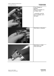
MOBILE COMMUNICATIONS DIVISION CUSTOMER SERVICES Tear off paper of 103 Place the Speaker on the Base Case. (remind:be care the pins of speaker, don't damage) Stick Mylar on Speaker Stick Mylar on USB Conn as shown Version 1.0 22/11/2006 Created by Konrad Szombara Page 44 of speaker.
MOBILE COMMUNICATIONS DIVISION CUSTOMER SERVICES Tear off paper of 103 Place the Speaker on the Base Case. (remind:be care the pins of speaker, don't damage) Stick Mylar on Speaker Stick Mylar on USB Conn as shown Version 1.0 22/11/2006 Created by Konrad Szombara Page 44 of speaker.

Service Manual
Page 46
MOBILE COMMUNICATIONS DIVISION CUSTOMER SERVICES Assemble USB into Base Case then assemble M/B to base case as shown Tear off tape paper of base case as shown then assemble K/B on base case Pls push the coaxial (antenna) cable to the bottom of M/B Version 1.0 22/11/2006 Created by Konrad Szombara Page 46 of 103
MOBILE COMMUNICATIONS DIVISION CUSTOMER SERVICES Assemble USB into Base Case then assemble M/B to base case as shown Tear off tape paper of base case as shown then assemble K/B on base case Pls push the coaxial (antenna) cable to the bottom of M/B Version 1.0 22/11/2006 Created by Konrad Szombara Page 46 of 103

Service Manual
Page 58
Wait until "Press Power is showing 3 - Disconnect the download cable from the mobile Version 1.0 22/11/2006 Created by Konrad Szombara Page 58 of 103 Click Reset when finished 5 - Load the specific configuration file and check the configuration 2 - MOBILE COMMUNICATIONS DIVISION CUSTOMER SERVICES When you have connected the cable to the handset, switch it on screen 4 - Long press mobile power key and follow the indication on and the USB connection will detect automatically. 1 4 23 1 -
Wait until "Press Power is showing 3 - Disconnect the download cable from the mobile Version 1.0 22/11/2006 Created by Konrad Szombara Page 58 of 103 Click Reset when finished 5 - Load the specific configuration file and check the configuration 2 - MOBILE COMMUNICATIONS DIVISION CUSTOMER SERVICES When you have connected the cable to the handset, switch it on screen 4 - Long press mobile power key and follow the indication on and the USB connection will detect automatically. 1 4 23 1 -
Service Manual
Page 80
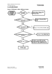
MOBILE COMMUNICATIONS DIVISION CUSTOMER SERVICES 7.1.2 FLASH FAILED Cause : PCB dead or Min. USB has broken Version 1.0 22/11/2006 Created by Konrad Szombara Page 80 of 103
MOBILE COMMUNICATIONS DIVISION CUSTOMER SERVICES 7.1.2 FLASH FAILED Cause : PCB dead or Min. USB has broken Version 1.0 22/11/2006 Created by Konrad Szombara Page 80 of 103
Service Manual
Page 83
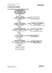
USB has broken Version 1.0 22/11/2006 Created by Konrad Szombara Page 83 of 103 MOBILE COMMUNICATIONS DIVISION CUSTOMER SERVICES 7.1.5 WILL NOT CHARGE Cause: PCB dead or Mini.
USB has broken Version 1.0 22/11/2006 Created by Konrad Szombara Page 83 of 103 MOBILE COMMUNICATIONS DIVISION CUSTOMER SERVICES 7.1.5 WILL NOT CHARGE Cause: PCB dead or Mini.
Service Manual
Page 89
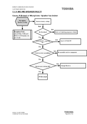
Yes PCBA dead NO Change Receiver Version 1.0 22/11/2006 Created by Konrad Szombara Page 89 of 103 NO Re-assemble receiver component Yes Check receiver being OK? NO repair ACF B2B FPC Yes Check receiver assembling? MOBILE COMMUNICATIONS DIVISION CUSTOMER SERVICES 7.1.11 MIC AND SPEAKER FAULTY Cause: PCB dead or Microphone / Speaker has broken Microphone Speaker Testing Earphone Fail , check Mini. USB port Refer to (Charging can not work) Restore factory setting Fail Re-Download NO Refer to (Updating program is failed) Yes Check B2B FPC connecting OK ?
Yes PCBA dead NO Change Receiver Version 1.0 22/11/2006 Created by Konrad Szombara Page 89 of 103 NO Re-assemble receiver component Yes Check receiver being OK? NO repair ACF B2B FPC Yes Check receiver assembling? MOBILE COMMUNICATIONS DIVISION CUSTOMER SERVICES 7.1.11 MIC AND SPEAKER FAULTY Cause: PCB dead or Microphone / Speaker has broken Microphone Speaker Testing Earphone Fail , check Mini. USB port Refer to (Charging can not work) Restore factory setting Fail Re-Download NO Refer to (Updating program is failed) Yes Check B2B FPC connecting OK ?

Service Manual
Page 92
Mobile Communications Division Customer Services 7.2 CONNECTORS 7.2.1 Connectors on Board I USB Connector J500 RTC BAT 101 Battery Connector J201 Version 1.0 14/08/2006 Created by Konrad Szombara Page 92 of 103
Mobile Communications Division Customer Services 7.2 CONNECTORS 7.2.1 Connectors on Board I USB Connector J500 RTC BAT 101 Battery Connector J201 Version 1.0 14/08/2006 Created by Konrad Szombara Page 92 of 103