

User Manual
Page 13
...: 03-3457-4868 Device Authorization This device obtains the Technical Regulation Conformity Certification and the Technical Conditions Compliance Approval, and it belongs to 2,483.5 MHz. 3. 13 The indication shown below appears on this equipment. (1) (2) (3) 2.4FH1 (4) 1 2.4: This equipment uses a frequency of 2.4 GHz. 2 FH: This equipment uses FH-SS modulation. 3 The interference range.... ❖ Do not install the embedded wireless module into other device. ❖ 5.17 GHz to 5.23 GHz for indoor use only. The name of Japan. TOSHIBA Direct PC Monday -
...: 03-3457-4868 Device Authorization This device obtains the Technical Regulation Conformity Certification and the Technical Conditions Compliance Approval, and it belongs to 2,483.5 MHz. 3. 13 The indication shown below appears on this equipment. (1) (2) (3) 2.4FH1 (4) 1 2.4: This equipment uses a frequency of 2.4 GHz. 2 FH: This equipment uses FH-SS modulation. 3 The interference range.... ❖ Do not install the embedded wireless module into other device. ❖ 5.17 GHz to 5.23 GHz for indoor use only. The name of Japan. TOSHIBA Direct PC Monday -
User Manual
Page 53
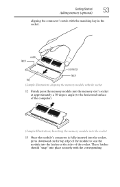
... the memory slot's socket at approximately a 30-degree angle (to the horizontal surface of the computer). (Sample Illustration) Inserting the memory module into the socket 13 Once the module's connector is fully inserted into the socket, press downward on the top edge of the module to seat the module into place...
... the memory slot's socket at approximately a 30-degree angle (to the horizontal surface of the computer). (Sample Illustration) Inserting the memory module into the socket 13 Once the module's connector is fully inserted into the socket, press downward on the top edge of the module to seat the module into place...
User Manual
Page 54
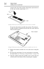
... surface before restarting the computer. latch latch (Sample Illustration) Pressing down on page 118. 16 Turn the computer right side up correctly, repeat steps 12-13. Back of the module. The memory module should be completely inserted into the socket and level when secured in the side of computer (Sample Illustration...
... surface before restarting the computer. latch latch (Sample Illustration) Pressing down on page 118. 16 Turn the computer right side up correctly, repeat steps 12-13. Back of the module. The memory module should be completely inserted into the socket and level when secured in the side of computer (Sample Illustration...