Maintenance Manual
Page 5
... more keys. For example: Read Only Memory (ROM) Keys Keys are used in the typeface below : DISKCOPY A: B: The display Text generated by a plus (+) sign. The key top symbol as it appears on its display is printed in the boldface type below : Format complete System transferred Satellite A110/Satellite Pro A110 Series Maintenance Manual [CONFIDENTIAL] v For...
... more keys. For example: Read Only Memory (ROM) Keys Keys are used in the typeface below : DISKCOPY A: B: The display Text generated by a plus (+) sign. The key top symbol as it appears on its display is printed in the boldface type below : Format complete System transferred Satellite A110/Satellite Pro A110 Series Maintenance Manual [CONFIDENTIAL] v For...
Maintenance Manual
Page 9
Chapter 4 Replacement Procedures 4.1 General...4-1 4.2 Battery...4-7 4.3 PC Card...4-8 4.4 HDD...4-10 4.5 Modem ...4-12 4.6 Expansion Memory...4-13 4.7 Wireless LAN Unit ...4-15 4.8 Optical Drive...4-18 4.9 Keyboard...4-20 4.10 Direct Assembly...4-22 4.11 Bluetooth...4-25 4.12 Top Cover ...4-26 4.13 Touch Pad ...4-28 4.14 System Board ...4-29 4.15 Speakers ...4-31 4.16 Thermal Module...4-32 4.17 CPU and Fan ...4-33 4.18 Display Mask ...4-35 4.19 LCD Module ...4-36 4.20 FL Inverter Board ...4-38 Satellite A110/Satellite Pro A110 Series Maintenance Manual [CONFIDENTIAL] ix
Chapter 4 Replacement Procedures 4.1 General...4-1 4.2 Battery...4-7 4.3 PC Card...4-8 4.4 HDD...4-10 4.5 Modem ...4-12 4.6 Expansion Memory...4-13 4.7 Wireless LAN Unit ...4-15 4.8 Optical Drive...4-18 4.9 Keyboard...4-20 4.10 Direct Assembly...4-22 4.11 Bluetooth...4-25 4.12 Top Cover ...4-26 4.13 Touch Pad ...4-28 4.14 System Board ...4-29 4.15 Speakers ...4-31 4.16 Thermal Module...4-32 4.17 CPU and Fan ...4-33 4.18 Display Mask ...4-35 4.19 LCD Module ...4-36 4.20 FL Inverter Board ...4-38 Satellite A110/Satellite Pro A110 Series Maintenance Manual [CONFIDENTIAL] ix

Maintenance Manual
Page 15
...Complementary Metal-Oxide Semiconductor (CMOS) technology extensively to 256MB shared with main memory (for more than 1G main memory) for ATI Radeon® XPRESS 200M ‰ Display • 15.4" TFT screen with main memory (for 512MB, 756MB main memory) for ATI Radeon® XPRESS 200M • Up to 128MB ...CODEC ‰ Video RAM • Up to 128MB integrated solution and shared with main memory for Mobile Intel 945GM Express Chipset • Up to 64MB shared with main memory (for 256MB main memory) for ATI Radeon® XPRESS 200M • Up to provide compact size, minimum weight...
...Complementary Metal-Oxide Semiconductor (CMOS) technology extensively to 256MB shared with main memory (for more than 1G main memory) for ATI Radeon® XPRESS 200M ‰ Display • 15.4" TFT screen with main memory (for 512MB, 756MB main memory) for ATI Radeon® XPRESS 200M • Up to 128MB ...CODEC ‰ Video RAM • Up to 128MB integrated solution and shared with main memory for Mobile Intel 945GM Express Chipset • Up to 64MB shared with main memory (for 256MB main memory) for ATI Radeon® XPRESS 200M • Up to provide compact size, minimum weight...
Maintenance Manual
Page 16
1 Hardware Overview 1.1 Features ‰ Memory • No on-board memory • Mobile Intel® 945GM Express Chipset with DDRII-533/667MHz • ATI Radeon® XPRESS 200M with DDRII-533MHz • Dual channel support • ...
1 Hardware Overview 1.1 Features ‰ Memory • No on-board memory • Mobile Intel® 945GM Express Chipset with DDRII-533/667MHz • ATI Radeon® XPRESS 200M with DDRII-533MHz • Dual channel support • ...
Maintenance Manual
Page 20
... LAN • Realtek ALC861 for HD CODEC ‰ Keyboard controller • ENE KB910 is use as keyboard controller and battery management unit. ‰ Memory • No on-board memory • Mobile Intel® 945GM Express Chipset with DDRII-533/667MHz • ATI Radeon® XPRESS 200M with DDRII-533MHz • Dual channel...
... LAN • Realtek ALC861 for HD CODEC ‰ Keyboard controller • ENE KB910 is use as keyboard controller and battery management unit. ‰ Memory • No on-board memory • Mobile Intel® 945GM Express Chipset with DDRII-533/667MHz • ATI Radeon® XPRESS 200M with DDRII-533MHz • Dual channel...

Maintenance Manual
Page 29
Status Charging Time (power on . The RTC battery is charged by the adaptor or main battery, while the computer is turned off. The table below lists the charging time and data preservation period of the RTC battery. 1.6 Batteries 1 Hardware Overview 1.6.2 RTC battery The RTC battery provides power to keep the current date, time and other setup information in memory while the computer is powered on ) Data preservation period (full charge) Time About 24 hours 1 month Detroit 20 /Detroit 20E Series Maintenance Manual [CONFIDENTIAL] 1-15
Status Charging Time (power on . The RTC battery is charged by the adaptor or main battery, while the computer is turned off. The table below lists the charging time and data preservation period of the RTC battery. 1.6 Batteries 1 Hardware Overview 1.6.2 RTC battery The RTC battery provides power to keep the current date, time and other setup information in memory while the computer is powered on ) Data preservation period (full charge) Time About 24 hours 1 month Detroit 20 /Detroit 20E Series Maintenance Manual [CONFIDENTIAL] 1-15
Maintenance Manual
Page 102
4 Replacement Procedures Chapter 4 Contents 4.1 General...4-1 4.2 Battery...4-7 4.3 PC Card...4-8 4.4 HDD...4-10 4.5 Modem ...4-12 4.6 Expansion Memory 4-13 4.7 Wireless LAN Unit 4-15 4.8 Optical Drive...4-18 4.9 Keyboard...4-20 4.10 Display Assembly ...4-22 4.11 Bluetooth...4-25 4.12 Top Cover ...4-26 4.13 TouchPad ...4-28 4.14 System Board ...4-29 4.15 Speakers ...4-31 4.16 Thermal Module...4-32 4.17 CPU and Fan ...4-33 4.18 Display Mask ...4-35 4.19 LCD Module ...4-36 4.20 FL Inverter Board ...4-38 Detroit 20 /Detroit 20E Series Maintenance Manual [CONFIDENTIAL] 4-iii
4 Replacement Procedures Chapter 4 Contents 4.1 General...4-1 4.2 Battery...4-7 4.3 PC Card...4-8 4.4 HDD...4-10 4.5 Modem ...4-12 4.6 Expansion Memory 4-13 4.7 Wireless LAN Unit 4-15 4.8 Optical Drive...4-18 4.9 Keyboard...4-20 4.10 Display Assembly ...4-22 4.11 Bluetooth...4-25 4.12 Top Cover ...4-26 4.13 TouchPad ...4-28 4.14 System Board ...4-29 4.15 Speakers ...4-31 4.16 Thermal Module...4-32 4.17 CPU and Fan ...4-33 4.18 Display Mask ...4-35 4.19 LCD Module ...4-36 4.20 FL Inverter Board ...4-38 Detroit 20 /Detroit 20E Series Maintenance Manual [CONFIDENTIAL] 4-iii
Maintenance Manual
Page 103
... the PC card 4-9 HDD ...4-10 Removing the HDD unit 4-10 Removing the EMI Shielding 4-11 Removing the modem screws 4-12 Removing the expansion memory 4-13 Installing the expansion memory 4-14 Removing the wireless LAN door 4-15 Removing the wireless LAN antenna wires 4-15 Removing the wireless LAN unit screws 4-16 Removing the...
... the PC card 4-9 HDD ...4-10 Removing the HDD unit 4-10 Removing the EMI Shielding 4-11 Removing the modem screws 4-12 Removing the expansion memory 4-13 Installing the expansion memory 4-14 Removing the wireless LAN door 4-15 Removing the wireless LAN antenna wires 4-15 Removing the wireless LAN unit screws 4-16 Removing the...
Maintenance Manual
Page 106
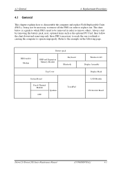
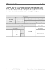
... the example on the following page. The chart below is causing the computer to operate improperly. HDD and/or Modem Battery pack ODD and Expansion Memory Module Keyboard Bluetooth Top Cover System Board Fan & Thermal Module CPU Speakers TouchPad Wireless LAN Display Assembly Display Mask LCD Module FL Inverter Board Detroit...
... the example on the following page. The chart below is causing the computer to operate improperly. HDD and/or Modem Battery pack ODD and Expansion Memory Module Keyboard Bluetooth Top Cover System Board Fan & Thermal Module CPU Speakers TouchPad Wireless LAN Display Assembly Display Mask LCD Module FL Inverter Board Detroit...
Maintenance Manual
Page 107
The Speakers are overlapped by removing the battery pack. HDD and/or Modem Battery pack ODD and Expansion Memory Module Keyboard Bluetooth Top Cover System Board Fan & Thermal Module CPU Speakers TouchPad Wireless LAN Display Assembly Display Mask LCD Module FL Inverter Board 4-2 [CONFIDENTIAL] ...
The Speakers are overlapped by removing the battery pack. HDD and/or Modem Battery pack ODD and Expansion Memory Module Keyboard Bluetooth Top Cover System Board Fan & Thermal Module CPU Speakers TouchPad Wireless LAN Display Assembly Display Mask LCD Module FL Inverter Board 4-2 [CONFIDENTIAL] ...
Maintenance Manual
Page 118
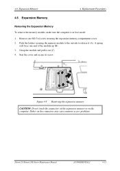
... out (C). 4. A spring will force one M2.5x4 screw securing the expansion memory compartment cover. 2. Grasp the module and pull it (A). Figure 4-8 Removing the expansion memory CAUTION: Do not touch the connectors on the expansion memory or on the connectors may cause memory access problems. Detroit 20 /Detroit 20E Series Maintenance Manual [CONFIDENTIAL] 4-13 Seat...
... out (C). 4. A spring will force one M2.5x4 screw securing the expansion memory compartment cover. 2. Grasp the module and pull it (A). Figure 4-8 Removing the expansion memory CAUTION: Do not touch the connectors on the expansion memory or on the connectors may cause memory access problems. Detroit 20 /Detroit 20E Series Maintenance Manual [CONFIDENTIAL] 4-13 Seat...

Maintenance Manual
Page 119
... [CONFIDENTIAL] Detroit 20 /Detroit 20E Series Maintenance Manual 4 Replacement Procedures 4.6 Expansion Memory Installing the Expansion Memory CAUTION: Do not touch the connectors on the expansion memory or on the connectors may cause memory access problems. To install a memory module, follow the steps below and refer to the figures in the preceding section: 1. Push the module...
... [CONFIDENTIAL] Detroit 20 /Detroit 20E Series Maintenance Manual 4 Replacement Procedures 4.6 Expansion Memory Installing the Expansion Memory CAUTION: Do not touch the connectors on the expansion memory or on the connectors may cause memory access problems. To install a memory module, follow the steps below and refer to the figures in the preceding section: 1. Push the module...
Maintenance Manual
Page 131
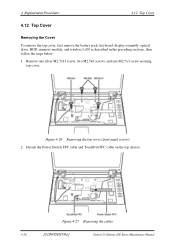
... 4.12 Top Cover 4.12 Top Cover Removing the Cover To remove the top cover, first remove the battery pack, keyboard, display assembly, optical drive, HDD, memory module, and wireless LAN as described in the preceding sections, then follow the steps below: 1. Detach the Power Switch FFC cable and TouchPad FFC cable...
... 4.12 Top Cover 4.12 Top Cover Removing the Cover To remove the top cover, first remove the battery pack, keyboard, display assembly, optical drive, HDD, memory module, and wireless LAN as described in the preceding sections, then follow the steps below: 1. Detach the Power Switch FFC cable and TouchPad FFC cable...


