User Manual
Page 50
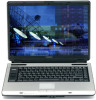
...charged battery can be used to select a power level setting that , the battery will allow the battery to power the computer, you must charge the battery. TECHNICAL NOTE: When your computer is not receiving correct input from the AC power supply. 50 Getting Started Charging the main battery ...NOTE If the AC power light flashes amber during charging, either the main battery is malfunctioning, or it is using the ...
...charged battery can be used to select a power level setting that , the battery will allow the battery to power the computer, you must charge the battery. TECHNICAL NOTE: When your computer is not receiving correct input from the AC power supply. 50 Getting Started Charging the main battery ...NOTE If the AC power light flashes amber during charging, either the main battery is malfunctioning, or it is using the ...
User Manual
Page 114
...off light ( ), and the power button light (near the upper left corner of the keyboard. NOTE If the AC power light flashes amber during charging, either the battery pack is malfunctioning, or it is not receiving correct input from the AC power supply. NOTE Battery life and charge ...time may vary, depending upon power management settings, applications and features used. ❖ Flashes amber when the main battery charge is low ...
...off light ( ), and the power button light (near the upper left corner of the keyboard. NOTE If the AC power light flashes amber during charging, either the battery pack is malfunctioning, or it is not receiving correct input from the AC power supply. NOTE Battery life and charge ...time may vary, depending upon power management settings, applications and features used. ❖ Flashes amber when the main battery charge is low ...
User Manual
Page 125
... should glow blue, and the battery light should glow amber to indicate that the battery pack is being supplied. Check the connections for the AC adapter and power cord/cable. 5 Charge the battery pack until the battery pack is some other warning to indicate a low battery, go to step 4. 3 ...Operate the computer on the computer's power. Overcharging makes the battery hot and shortens its life. ❖ If you will not be using the system for an extended period, more than one...
... should glow blue, and the battery light should glow amber to indicate that the battery pack is being supplied. Check the connections for the AC adapter and power cord/cable. 5 Charge the battery pack until the battery pack is some other warning to indicate a low battery, go to step 4. 3 ...Operate the computer on the computer's power. Overcharging makes the battery hot and shortens its life. ❖ If you will not be using the system for an extended period, more than one...
User Manual
Page 243
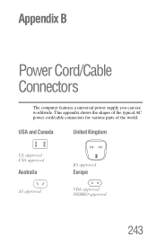
Appendix B Power Cord/Cable Connectors The computer features a universal power supply you can use worldwide. USA and Canada United Kingdom UL approved CSA approved Australia AS approved BS approved Europe VDA approved NEMKO approved 243 This appendix shows the shapes of the typical AC power cord/cable connectors for various parts of the world.
Appendix B Power Cord/Cable Connectors The computer features a universal power supply you can use worldwide. USA and Canada United Kingdom UL approved CSA approved Australia AS approved BS approved Europe VDA approved NEMKO approved 243 This appendix shows the shapes of the typical AC power cord/cable connectors for various parts of the world.
User Manual
Page 287
... 48 energy-saving features 108 problem solving 201 turning on 52 universal power supply 243 power button 52 Power Management 165 power mode creating new 166 customizing 166 power source 47 connecting 48 power usage mode hot key 119 power usage modes 118 powering down using Standby 79, 81 precautions 41 primary button 62, 65... printer local, connecting 71 problem solving 214 printing a file 96 problem solving AC power 201 accessing disk drives 192 battery charge does not last 202 battery not charging 201 cannot insert diskette in drive 208 cannot read a...
... 48 energy-saving features 108 problem solving 201 turning on 52 universal power supply 243 power button 52 Power Management 165 power mode creating new 166 customizing 166 power source 47 connecting 48 power usage mode hot key 119 power usage modes 118 powering down using Standby 79, 81 precautions 41 primary button 62, 65... printer local, connecting 71 problem solving 214 printing a file 96 problem solving AC power 201 accessing disk drives 192 battery charge does not last 202 battery not charging 201 cannot insert diskette in drive 208 cannot read a...

User Manual
Page 30
... item in the computer's intelligent power supply detects the battery's charge and calculates the remaining battery capacity. You can specify the setting in the Setup Action tab in TOSHIBA Power Saver. You can specify the setting in the When I close the lid item of the Setup Action tab in TOSHIBA Power Saver. To protect from your...
... item in the computer's intelligent power supply detects the battery's charge and calculates the remaining battery capacity. You can specify the setting in the Setup Action tab in TOSHIBA Power Saver. You can specify the setting in the When I close the lid item of the Setup Action tab in TOSHIBA Power Saver. To protect from your...

User Manual
Page 42
...battery indicator shows the condition of the charge. Disk The Disk indicator glows blue when the computer is supplied from the AC power adaptor. User's Manual 2-9 Power The Power indicator glows blue when the computer is accessing the Multiple Digital slot Media Card Slot. If you turn..., this indicator flashes amber. If the adaptor's output voltage is abnormal or if the power supply malfunctions, this indicator blinks amber while the computer shuts down. Refer to Chapter 6, Power and PowerUp Modes. Mutiple digital The Multiple digital Media Card Slot indicator glows blue media ...
...battery indicator shows the condition of the charge. Disk The Disk indicator glows blue when the computer is supplied from the AC power adaptor. User's Manual 2-9 Power The Power indicator glows blue when the computer is accessing the Multiple Digital slot Media Card Slot. If you turn..., this indicator flashes amber. If the adaptor's output voltage is abnormal or if the power supply malfunctions, this indicator blinks amber while the computer shuts down. Refer to Chapter 6, Power and PowerUp Modes. Mutiple digital The Multiple digital Media Card Slot indicator glows blue media ...

User Manual
Page 108
... of the computer away from an AC power source. Plug the AC adaptor into another outlet. Power and Power-Up Modes DC IN indicator Check the DC IN indicator to determine the power status with the power supply. Power indicator Check the Power indicator to the computer. No light Under...turned on. Use only batteries recommended by TOSHIBA as required by local ordinances or regulations. Indicates a problem with the AC adaptor connected: Blue Amber No light Indicates the AC adaptor is connected and supplying proper power to determine the power status. If it still does not operate...
... of the computer away from an AC power source. Plug the AC adaptor into another outlet. Power and Power-Up Modes DC IN indicator Check the DC IN indicator to determine the power status with the power supply. Power indicator Check the Power indicator to the computer. No light Under...turned on. Use only batteries recommended by TOSHIBA as required by local ordinances or regulations. Indicates a problem with the AC adaptor connected: Blue Amber No light Indicates the AC adaptor is connected and supplying proper power to determine the power status. If it still does not operate...

User Manual
Page 135
Turn the computer on . 4. TOSHIBA assumes no liability for a range of digital video transfer. Connect all devices to the video out port. Digital video cameras 2. CD-RW drives i.LINK uses a ... Turn the television on . You may not use any copyrighted video or music data copied from another i.LINK device that data will need their own power supply. If you turn on the computer's power. 4. Use a video cable (not supplied) to connect the television to the hub before transferring it to electronic noise.
Turn the computer on . 4. TOSHIBA assumes no liability for a range of digital video transfer. Connect all devices to the video out port. Digital video cameras 2. CD-RW drives i.LINK uses a ... Turn the television on . You may not use any copyrighted video or music data copied from another i.LINK device that data will need their own power supply. If you turn on the computer's power. 4. Use a video cable (not supplied) to connect the television to the hub before transferring it to electronic noise.

User Manual
Page 141
... are interrelated and any one could lie with Tomorrow TOSHIBA This message remains on the screen, and the system does not function normally. ■ The screen displays an error message. If any of other power resources, including intelligent power supply and Real Time Clock battery. Power When the computer is not plugged into an AC...
... are interrelated and any one could lie with Tomorrow TOSHIBA This message remains on the screen, and the system does not function normally. ■ The screen displays an error message. If any of other power resources, including intelligent power supply and Real Time Clock battery. Power When the computer is not plugged into an AC...
Maintenance Manual
Page 7
... 20 1.1.3 RTC Battery 21 Chapter 2 Troubleshooting 2.1 Outline ...2-1 2.2 Basic Flowchart...2-2 2.3 Power Supply...2-6 Procedure 1 Power Icon Check 2-6 Procedure 2 Connection Check 2-8 Procedure 3 Replacement Check 2-8 2.4 System Board...2-9 Procedure 3 Replacement Check 2-10 2.5 2.5-inch HDD ...2-11 Procedure 1 Message Check 2-11 Procedure 2 Partition Check 2-11 Procedure 3 Format Check 2-12 Procedure 4 Test Program Check 2-13 Satellite A100/A105 / TECRA A7 Maintenance Manual vii
... 20 1.1.3 RTC Battery 21 Chapter 2 Troubleshooting 2.1 Outline ...2-1 2.2 Basic Flowchart...2-2 2.3 Power Supply...2-6 Procedure 1 Power Icon Check 2-6 Procedure 2 Connection Check 2-8 Procedure 3 Replacement Check 2-8 2.4 System Board...2-9 Procedure 3 Replacement Check 2-10 2.5 2.5-inch HDD ...2-11 Procedure 1 Message Check 2-11 Procedure 2 Partition Check 2-11 Procedure 3 Format Check 2-12 Procedure 4 Test Program Check 2-13 Satellite A100/A105 / TECRA A7 Maintenance Manual vii
Maintenance Manual
Page 17
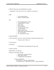
1 Hardware Overview Chapter 1 Contents 1.1 Features...1 1.2 System Unit Components...9 1.3 2.5-inch HDD...15 1.4 DVD-ROM Drive...16 1.5 CD-RW/DVD-ROM Drive 17 1.6 DVD Super Multi (+-R Double Layer 18 1.7 Power Supply ...19 1.8 Batteries ...20 1.1.1 Main Battery 20 1.1.2 Battery Charging Control 20 1.1.3 RTC Battery 21 Satellite A100/A105 / TECRA A7 Maintenance Manual iii
1 Hardware Overview Chapter 1 Contents 1.1 Features...1 1.2 System Unit Components...9 1.3 2.5-inch HDD...15 1.4 DVD-ROM Drive...16 1.5 CD-RW/DVD-ROM Drive 17 1.6 DVD Super Multi (+-R Double Layer 18 1.7 Power Supply ...19 1.8 Batteries ...20 1.1.1 Main Battery 20 1.1.2 Battery Charging Control 20 1.1.3 RTC Battery 21 Satellite A100/A105 / TECRA A7 Maintenance Manual iii
Maintenance Manual
Page 31
... Cooling fan speed control ? I2C communication control ? ? Modem Controller ?Built-in the battery pack ? Scan controller function ? Power supply sequence control ? Overheat shutdown support ? Battery capacity check ? Battery EE PROM ? 24C02 equivalent (128 words x 16 bits,... For data communication: V.90(China)/V.92 data rates: 28kbps/56kbps V.34 Extended rates: 33.6K/2400/V.32 turbo, V.32bits,and fallbacks Satellite A100/A105 / TECRA A7 Maintenance Manual 13 Clock Generator ? Storing records of the modem controller: ? EC access interface ? 1.2 System Unit ...
... Cooling fan speed control ? I2C communication control ? ? Modem Controller ?Built-in the battery pack ? Scan controller function ? Power supply sequence control ? Overheat shutdown support ? Battery capacity check ? Battery EE PROM ? 24C02 equivalent (128 words x 16 bits,... For data communication: V.90(China)/V.92 data rates: 28kbps/56kbps V.34 Extended rates: 33.6K/2400/V.32 turbo, V.32bits,and fallbacks Satellite A100/A105 / TECRA A7 Maintenance Manual 13 Clock Generator ? Storing records of the modem controller: ? EC access interface ? 1.2 System Unit ...
Maintenance Manual
Page 37
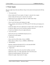
... from the AC adapter. Satellite A100/A105 / TECRA A7 Maintenance Manual 19 Power input monitor ? Issues a charging current instruction to the computer. ? Performs communication through the I2C bus (via the internal EC/KBC). ? Monitors the DC power supply input voltage (AC Adapter output voltage). 2. Power supply's internal control ? External interface ? 1.7 Power Supply 1 Hardware Overview 1.7 Power Supply The power supply unit provides many different...
... from the AC adapter. Satellite A100/A105 / TECRA A7 Maintenance Manual 19 Power input monitor ? Issues a charging current instruction to the computer. ? Performs communication through the I2C bus (via the internal EC/KBC). ? Monitors the DC power supply input voltage (AC Adapter output voltage). 2. Power supply's internal control ? External interface ? 1.7 Power Supply 1 Hardware Overview 1.7 Power Supply The power supply unit provides many different...

Maintenance Manual
Page 41
2 Troubleshooting Chapter 2 Contents 2.1 Outline ...2-1 2.2 Basic Flowchart ...2-2 2.3 Power Supply...2-6 Procedure 1 Power Icon Check 2-6 Procedure 2 Connection Check 2-8 Procedure 3 Replacement Check 2-8 2.4 System Board...2-9 Procedure 3 Replacement Check 2-11 2.5 2.5-inch HDD ...2-12 Procedure 1 Message Check 2-12 Procedure 2 Partition Check 2-12 ... Check 2-22 Procedure 2Connector Check and Replacement Check 2-22 2.10 SD/MS/MS pro/MMC/XD Card(Optional 2-23 Procedure 1Test Program Check 2-23 2-ii Satellite A100/A105 / TECRA A7 Maintenance Manual
2 Troubleshooting Chapter 2 Contents 2.1 Outline ...2-1 2.2 Basic Flowchart ...2-2 2.3 Power Supply...2-6 Procedure 1 Power Icon Check 2-6 Procedure 2 Connection Check 2-8 Procedure 3 Replacement Check 2-8 2.4 System Board...2-9 Procedure 3 Replacement Check 2-11 2.5 2.5-inch HDD ...2-12 Procedure 1 Message Check 2-12 Procedure 2 Partition Check 2-12 ... Check 2-22 Procedure 2Connector Check and Replacement Check 2-22 2.10 SD/MS/MS pro/MMC/XD Card(Optional 2-23 Procedure 1Test Program Check 2-23 2-ii Satellite A100/A105 / TECRA A7 Maintenance Manual

Maintenance Manual
Page 46
... Toshiba" displayed Yes Follow the system board diagnostic procedure in Section 2.4 No Follow the display diagnostic procedure in Section 2.3 Any error message displayed ?? No Follow the power supply diagnostic procedure in Section 2.3 No Follow the power supply ...diagnostic procedure in Section 2.7 Yes "Password=" displayed ?? Yes 1 Figure 2-1 Follow the HDD diagnostic procedure in Section 2.5 No Basic flowchart(1/2) Satellite A100/A105 / TECRA A7 Maintenance Manual 2-3 Yes Turn the power...
... Toshiba" displayed Yes Follow the system board diagnostic procedure in Section 2.4 No Follow the display diagnostic procedure in Section 2.3 Any error message displayed ?? No Follow the power supply diagnostic procedure in Section 2.3 No Follow the power supply ...diagnostic procedure in Section 2.7 Yes "Password=" displayed ?? Yes 1 Figure 2-1 Follow the HDD diagnostic procedure in Section 2.5 No Basic flowchart(1/2) Satellite A100/A105 / TECRA A7 Maintenance Manual 2-3 Yes Turn the power...
Maintenance Manual
Page 49
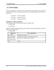
... the computer controls many functions and components. 2 Troubleshooting 2.3 Power Supply 2.3 Power Supply The power supply in Amber (at equal intervals) Off Power supply status Battery being charged Battery fully charged, with AC adapter connected Battery low *1 while driving the computer Else 2-6 Satellite A100/A105 / TECRA A7 Maintenance Manual To check if the power supply is defective or malfunctioning, follow the troubleshooting procedures...
... the computer controls many functions and components. 2 Troubleshooting 2.3 Power Supply 2.3 Power Supply The power supply in Amber (at equal intervals) Off Power supply status Battery being charged Battery fully charged, with AC adapter connected Battery low *1 while driving the computer Else 2-6 Satellite A100/A105 / TECRA A7 Maintenance Manual To check if the power supply is defective or malfunctioning, follow the troubleshooting procedures...
Maintenance Manual
Page 50
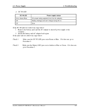
Else If the DC IN LED off, follow the steps below : 1. If the LED still off power supply to Procedure 3. If it does not, go to the computer. 2. Satellite A100/A105 / TECRA A7 Maintenance Manual 2-7 Remove the battery pack and the AC adapter to Procedure 2. Attach the battery and AC adapter back again. Check 2 Make... sure the DC IN LED goes on in Amber or Blue or Green . DC IN LED DC IN LED On in Green/Blue Off Off Power supply status DC power being supplied (from the AC adapter) Battery damage and can't charge during DC-in Green or Blue...
Else If the DC IN LED off, follow the steps below : 1. If the LED still off power supply to Procedure 3. If it does not, go to the computer. 2. Satellite A100/A105 / TECRA A7 Maintenance Manual 2-7 Remove the battery pack and the AC adapter to Procedure 2. Attach the battery and AC adapter back again. Check 2 Make... sure the DC IN LED goes on in Amber or Blue or Green . DC IN LED DC IN LED On in Green/Blue Off Off Power supply status DC power being supplied (from the AC adapter) Battery damage and can't charge during DC-in Green or Blue...

Maintenance Manual
Page 51
Procedure 3 Replacement Check The system board, power supply board, or CPU may be faulty. Check 2 Replace the system board with a new one. 2-8 Satellite A100/A105 / TECRA A7 Maintenance Manual If the battery pack is still not working properly, perform Check ... the CPU with a new one . 2 Troubleshooting 2.3 Power Supply Procedure 2 Connection Check Power is supplied to the system board as illustrated below: AC adaptor System board AC power cord AC adaptor cord Battery pack Follow the steps below : Check 1 Replace the power supply board with a new one . Check 2 Connect a ...
Procedure 3 Replacement Check The system board, power supply board, or CPU may be faulty. Check 2 Replace the system board with a new one. 2-8 Satellite A100/A105 / TECRA A7 Maintenance Manual If the battery pack is still not working properly, perform Check ... the CPU with a new one . 2 Troubleshooting 2.3 Power Supply Procedure 2 Connection Check Power is supplied to the system board as illustrated below: AC adaptor System board AC power cord AC adaptor cord Battery pack Follow the steps below : Check 1 Replace the power supply board with a new one . Check 2 Connect a ...

Maintenance Manual
Page 155
... When you partially disassemble the computer and turn the computer off and remove the AC adapter from the electrical outlet. Never work . Satellite A100/A105 / TECRA A7 Maintenance Manual 4-3 Batteries other than those differ in the computer is left charged, the risk of electrical shock remains..., be sure to remove any metal jewelry or accessories such as the power supply and FL inverter carry high voltages. To avoid personal injury, use the genuine batteries or replacement batteries authorized by Toshiba. To avoid leakage of the components. They may burst or explode. ...
... When you partially disassemble the computer and turn the computer off and remove the AC adapter from the electrical outlet. Never work . Satellite A100/A105 / TECRA A7 Maintenance Manual 4-3 Batteries other than those differ in the computer is left charged, the risk of electrical shock remains..., be sure to remove any metal jewelry or accessories such as the power supply and FL inverter carry high voltages. To avoid personal injury, use the genuine batteries or replacement batteries authorized by Toshiba. To avoid leakage of the components. They may burst or explode. ...


