Maintenance Manual
Page 3
... to perform hardware service maintenance for the Toshiba Personal Computer PORTEGE R600 The procedures described in this manual to bring important information to your safe maintenance service. CAUTION: "Caution" indicates the existence of messages are used in this manual are adhered to strictly. ‰ Be sure to your attention. SAFETY PRECAUTIONS Four types of a hazard that relates to fasten screws securely...
... to perform hardware service maintenance for the Toshiba Personal Computer PORTEGE R600 The procedures described in this manual to bring important information to your safe maintenance service. CAUTION: "Caution" indicates the existence of messages are used in this manual are adhered to strictly. ‰ Be sure to your attention. SAFETY PRECAUTIONS Four types of a hazard that relates to fasten screws securely...

Maintenance Manual
Page 8
... Test ...3-25 3.13 Hard Disk Test ...3-26 3.14 Real Timer Test...3-29 3.15 NDP Test...3-31 3.16 Expansion Test...3-32 3.17 CD-ROM/DVD-ROM Test 3-34 3.18 Error Code and Error Status Names 3-35 3.19 Hard Disk Test Detail Status 3-38 3.20 ONLY ONE TEST 3-40 3.21 Head Cleaning...3-51 3.22 Log Utilities ...3-52 3.23 Running Test...3-54 3.24 Floppy Disk Drive Utilities 3-55 3.25 System Configuration 3-60 3.26 Wireless LAN Test...
... Test ...3-25 3.13 Hard Disk Test ...3-26 3.14 Real Timer Test...3-29 3.15 NDP Test...3-31 3.16 Expansion Test...3-32 3.17 CD-ROM/DVD-ROM Test 3-34 3.18 Error Code and Error Status Names 3-35 3.19 Hard Disk Test Detail Status 3-38 3.20 ONLY ONE TEST 3-40 3.21 Head Cleaning...3-51 3.22 Log Utilities ...3-52 3.23 Running Test...3-54 3.24 Floppy Disk Drive Utilities 3-55 3.25 System Configuration 3-60 3.26 Wireless LAN Test...

Maintenance Manual
Page 31
... a hard disk drive. 1 Hardware Overview 1.5 1.8-inch Solid State Drive (SSD) Some models are listed by the table 1-3. Table 1-3 1.8-inch Solid State Drive (SSD) specifications Items Outline Dimensions Width (mm) Height (mm) Depth (mm) Weigh t (g) Storage size (formatted) Data transfer speed TOSHIBA G8BC0004X641 Specifications TOSHIBA G8BC0004X121 53.60 3.0 70.6 15 64GB 128GB. The computer supports a 64GB and 128GB. Host Interface : Max 300MB/s Sustained Data Read : Max 100MB/s Sustained Data Write : Max 40MB/s PORTEGE R600 Maintenance Manual (960...
... a hard disk drive. 1 Hardware Overview 1.5 1.8-inch Solid State Drive (SSD) Some models are listed by the table 1-3. Table 1-3 1.8-inch Solid State Drive (SSD) specifications Items Outline Dimensions Width (mm) Height (mm) Depth (mm) Weigh t (g) Storage size (formatted) Data transfer speed TOSHIBA G8BC0004X641 Specifications TOSHIBA G8BC0004X121 53.60 3.0 70.6 15 64GB 128GB. The computer supports a 64GB and 128GB. Host Interface : Max 300MB/s Sustained Data Read : Max 100MB/s Sustained Data Write : Max 40MB/s PORTEGE R600 Maintenance Manual (960...

Maintenance Manual
Page 47
... configuration in Chapter 3. Also update with the latest EC/KBC as described in Appendix H "EC/KBC Rewrite Procedures" to set the SVP parameter. USB FDD 4. Wireless LAN 12. Intel Turbo Memory The Test Program operations are described in Appendix H "EC/KBC Rewrite Procedures". Also, following implements are : 1. Display 8. Optical Disk Drive 9. 2.1 Troubleshooting 2 Troubleshooting Procedures 2 2.1 Troubleshooting Chapter 2 describes how to determine which Field Replaceable...
... configuration in Chapter 3. Also update with the latest EC/KBC as described in Appendix H "EC/KBC Rewrite Procedures" to set the SVP parameter. USB FDD 4. Wireless LAN 12. Intel Turbo Memory The Test Program operations are described in Appendix H "EC/KBC Rewrite Procedures". Also, following implements are : 1. Display 8. Optical Disk Drive 9. 2.1 Troubleshooting 2 Troubleshooting Procedures 2 2.1 Troubleshooting Chapter 2 describes how to determine which Field Replaceable...
Maintenance Manual
Page 56
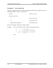
2 Troubleshooting Procedures 2.3 Power Supply Troubleshooting Procedure 2 Error Code Check If the power supply microprocessor detects a malfunction, the DC IN icon blinks orange. The blink pattern indicates an error as shown below. ‰ Start Off for 2 seconds ‰ Error code (8 bit) "1" On for one second "0" On for half second Interval between data bits Off for half second The error code begins with the least significant digit. Example: Error code 11h (Error codes are given in hexadecimal format.) Start 2-10 [CONFIDENTIAL] PORTEGE R600 Maintenance Manual (960-709)
2 Troubleshooting Procedures 2.3 Power Supply Troubleshooting Procedure 2 Error Code Check If the power supply microprocessor detects a malfunction, the DC IN icon blinks orange. The blink pattern indicates an error as shown below. ‰ Start Off for 2 seconds ‰ Error code (8 bit) "1" On for one second "0" On for half second Interval between data bits Off for half second The error code begins with the least significant digit. Example: Error code 11h (Error codes are given in hexadecimal format.) Start 2-10 [CONFIDENTIAL] PORTEGE R600 Maintenance Manual (960-709)
Maintenance Manual
Page 59
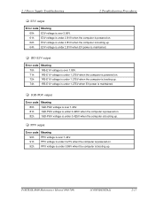
2.3 Power Supply Troubleshooting 2 Troubleshooting Procedures ‰ E3V output Error code Meaning 60h E3V voltage is over 3.96V. 61h E3V voltage is under 2.81V when the computer is powered on. 62h E3V voltage is under 2.81V when the computer is booting up. 64h E3V voltage is under 2.81V when EV power is maintained. ‰ 1R5-E1V output Error code Meaning 70h 1R5-E1V voltage is over 1.80V. 71h...
2.3 Power Supply Troubleshooting 2 Troubleshooting Procedures ‰ E3V output Error code Meaning 60h E3V voltage is over 3.96V. 61h E3V voltage is under 2.81V when the computer is powered on. 62h E3V voltage is under 2.81V when the computer is booting up. 64h E3V voltage is under 2.81V when EV power is maintained. ‰ 1R5-E1V output Error code Meaning 70h 1R5-E1V voltage is over 1.80V. 71h...

Maintenance Manual
Page 60
2 Troubleshooting Procedures 2.3 Power Supply Troubleshooting ‰ 1R05-E1V output Error code A0h A1h A2h A4h Meaning 1R05-E1V voltage is over 1.26V. 1R05-E1V voltage is under 0.89V when the computer is powered on. 1R05-E1V voltage is under 0.89V when the computer is booting up. 1R05-E1V voltage is under 0.89V when EV power is maintained. ‰ 1R5-E1V output Error code B0h B1h B2h...
2 Troubleshooting Procedures 2.3 Power Supply Troubleshooting ‰ 1R05-E1V output Error code A0h A1h A2h A4h Meaning 1R05-E1V voltage is over 1.26V. 1R05-E1V voltage is under 0.89V when the computer is powered on. 1R05-E1V voltage is under 0.89V when the computer is booting up. 1R05-E1V voltage is under 0.89V when EV power is maintained. ‰ 1R5-E1V output Error code B0h B1h B2h...
Maintenance Manual
Page 66
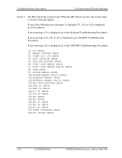
... ERROR (11) EXTENDED MEMORY ERROR (12) EXTENDED MEMORY PARITY ERROR (13) DMA PAGE REGISTER ERROR (14) DMAC #1 ERROR (15) DMAC #2 ERROR (16) PIC #1 ERROR (17) PIC #2 ERROR (18) KBC ERROR (19) HDC ERROR (20) HDD #0 ERROR (21) HDD #1 ERROR (22) NO FDD ERROR (23) TIMER INTERRUPT ERROR (24) RTC UPDATE ERROR 2-20 [CONFIDENTIAL] PORTEGE R600 Maintenance Manual (960-709) If error message (22) is displayed, go to the Keyboard Troubleshooting Procedures. If error...
... ERROR (11) EXTENDED MEMORY ERROR (12) EXTENDED MEMORY PARITY ERROR (13) DMA PAGE REGISTER ERROR (14) DMAC #1 ERROR (15) DMAC #2 ERROR (16) PIC #1 ERROR (17) PIC #2 ERROR (18) KBC ERROR (19) HDC ERROR (20) HDD #0 ERROR (21) HDD #1 ERROR (22) NO FDD ERROR (23) TIMER INTERRUPT ERROR (24) RTC UPDATE ERROR 2-20 [CONFIDENTIAL] PORTEGE R600 Maintenance Manual (960-709) If error message (22) is displayed, go to the Keyboard Troubleshooting Procedures. If error...

Maintenance Manual
Page 83
... the computer. If the problem still occurs, go to Check 3. Otherwise, the 2.5" HDD is listed as active in the Display Partition Information, go to the User's Manual. Procedure 1: Partition Check Procedure 2: Message Check Procedure 3: Format Check Procedure 4: Diagnostic Test Program Execution Check Procedure 5: Connector Check and Replacement Check CAUTION: The contents of the hard disk to Procedure 2. If you can change to drive C, go to Check...
... the computer. If the problem still occurs, go to Check 3. Otherwise, the 2.5" HDD is listed as active in the Display Partition Information, go to the User's Manual. Procedure 1: Partition Check Procedure 2: Message Check Procedure 3: Format Check Procedure 4: Diagnostic Test Program Execution Check Procedure 5: Connector Check and Replacement Check CAUTION: The contents of the hard disk to Procedure 2. If you can change to drive C, go to Check...
Maintenance Manual
Page 114
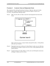
... 1 Make sure the cables are firmly connected to Check 2. If the problem still occurs, perform Check 3. If the connection is loose, reconnect firmly and repeat Procedure 1. 2 Troubleshooting Procedures 2.17 Fingerprint sensor Troubleshooting Procedure 4 Connector Check and Replacement Check The connection of the cable and board may be faulty. Check 3 System board may be defective. Replace it with a new one following the instructions in Chapter 4, Replacement Procedures, and perform the...
... 1 Make sure the cables are firmly connected to Check 2. If the problem still occurs, perform Check 3. If the connection is loose, reconnect firmly and repeat Procedure 1. 2 Troubleshooting Procedures 2.17 Fingerprint sensor Troubleshooting Procedure 4 Connector Check and Replacement Check The connection of the cable and board may be faulty. Check 3 System board may be defective. Replace it with a new one following the instructions in Chapter 4, Replacement Procedures, and perform the...

Maintenance Manual
Page 115
... R600 Maintenance Manual (960-709) [CONFIDENTIAL] 2-69 Otherwise, they may be faulty. If the problem still occurs, perform Check 2. Procedure 2 Connector Check and Replacement Check The connection of the screen. 2.18 Web camera Troubleshooting 2 Troubleshooting Procedures 2.18 Web camera Troubleshooting To check if the computer's web camera is loose, reconnect it firmly and check each connection. Procedure 1: Check on Windows OS Procedure 2: Connector...
... R600 Maintenance Manual (960-709) [CONFIDENTIAL] 2-69 Otherwise, they may be faulty. If the problem still occurs, perform Check 2. Procedure 2 Connector Check and Replacement Check The connection of the screen. 2.18 Web camera Troubleshooting 2 Troubleshooting Procedures 2.18 Web camera Troubleshooting To check if the computer's web camera is loose, reconnect it firmly and check each connection. Procedure 1: Check on Windows OS Procedure 2: Connector...

Maintenance Manual
Page 121
... Diagnostic Test 3-4 3.2.1 Diagnostics menu (T&D 3-5 3.2.2 H/W initial information setting tool 3-8 3.2.3 Heatrun test program 3-8 3.3 Setting of the hardware configuration 3-9 3.4 Heatrun Test...3-11 3.5 Subtest Names...3-12 3.6 System Test...3-14 3.7 Memory Test...3-16 3.8 Keyboard Test...3-17 3.9 Display Test ...3-18 3.10 Floppy Disk Test...3-21 3.11 Printer Test...3-23 3.12 Async Test ...3-25 3.13 Hard Disk Test ...3-26 3.14 Real Timer Test...3-29 3.15 NDP Test...3-31 3.16 Expansion Test...3-32 3.17 CD-ROM/DVD-ROM Test 3-34 3.18 Error Code and Error...
... Diagnostic Test 3-4 3.2.1 Diagnostics menu (T&D 3-5 3.2.2 H/W initial information setting tool 3-8 3.2.3 Heatrun test program 3-8 3.3 Setting of the hardware configuration 3-9 3.4 Heatrun Test...3-11 3.5 Subtest Names...3-12 3.6 System Test...3-14 3.7 Memory Test...3-16 3.8 Keyboard Test...3-17 3.9 Display Test ...3-18 3.10 Floppy Disk Test...3-21 3.11 Printer Test...3-23 3.12 Async Test ...3-25 3.13 Hard Disk Test ...3-26 3.14 Real Timer Test...3-29 3.15 NDP Test...3-31 3.16 Expansion Test...3-32 3.17 CD-ROM/DVD-ROM Test 3-34 3.18 Error Code and Error...

Maintenance Manual
Page 126
...; A formatted working disk (Floppy disk test) ‰ A cleaning kit to clean the floppy disk drive heads (Head Cleaning) ‰ An external display supporting monitor ID (Expansion test) ‰ A CD test media TOSHIBA CD-ROM TEST DISK or ABEX TEST CD-ROM (Sound test) ‰ A DVD test media (DVD-ROM TEST DISK TSD-1) (Sound test) ‰ A music CD (Sound test) ‰ A CD-RW test media (CD-ROM/DVD-ROM test) ‰ A USB test module (USB test ) ‰ A USB cable (USB test) ‰ LAN wraparound connector...
...; A formatted working disk (Floppy disk test) ‰ A cleaning kit to clean the floppy disk drive heads (Head Cleaning) ‰ An external display supporting monitor ID (Expansion test) ‰ A CD test media TOSHIBA CD-ROM TEST DISK or ABEX TEST CD-ROM (Sound test) ‰ A DVD test media (DVD-ROM TEST DISK TSD-1) (Sound test) ‰ A music CD (Sound test) ‰ A CD-RW test media (CD-ROM/DVD-ROM test) ‰ A USB test module (USB test ) ‰ A USB cable (USB test) ‰ LAN wraparound connector...

Maintenance Manual
Page 132
... an error is found . Selecting NO keeps the test running even if an error is added to the section 3.4. 3-8 [CONFIDENTIAL] PORTEGE R600 Maintenance Manual (960-709) Table 3-1 in section 3.6 describes the function of each error. 3.2.2 H/W initial information setting tool After selecting this test, the following functions respectively: 1. Table 3-2 in the display. ###### Repair Initial config set #### * 1 Entry of the display screen as 3.23 RUNNING TEST. Use the...
... an error is found . Selecting NO keeps the test running even if an error is added to the section 3.4. 3-8 [CONFIDENTIAL] PORTEGE R600 Maintenance Manual (960-709) Table 3-1 in section 3.6 describes the function of each error. 3.2.2 H/W initial information setting tool After selecting this test, the following functions respectively: 1. Table 3-2 in the display. ###### Repair Initial config set #### * 1 Entry of the display screen as 3.23 RUNNING TEST. Use the...
Maintenance Manual
Page 159
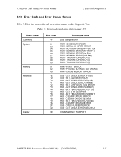
... error codes and error status names for the Diagnostic Test. CHECKSUM ERROR ROM - SERIAL ID WRITE ERROR ROM - CACHE MEMORY ERROR USB - GET DESCR.ERROR(Top 8B) HUB - CLEAR FEATURE1 ERROR HUB - PARITY ERROR RAM - GET STATUS ERROR HUB - SET FEATURE ERROR(Enab.) HUB - SENSING ERROR(AC-ADAPT) ROM - GET DESCR.ERROR (Whole) HUB - GET DESCR.ERROR(DESCR.) HUB - SENSING ERROR(2nd Batt) ROM - THORMISTOR ERROR(3) RAM - GET DESCR.ERROR(SECOND) VRAM SIZE NOT SUPPORT PORTEGE R600 Maintenance Manual...
... error codes and error status names for the Diagnostic Test. CHECKSUM ERROR ROM - SERIAL ID WRITE ERROR ROM - CACHE MEMORY ERROR USB - GET DESCR.ERROR(Top 8B) HUB - CLEAR FEATURE1 ERROR HUB - PARITY ERROR RAM - GET STATUS ERROR HUB - SET FEATURE ERROR(Enab.) HUB - SENSING ERROR(AC-ADAPT) ROM - GET DESCR.ERROR (Whole) HUB - GET DESCR.ERROR(DESCR.) HUB - SENSING ERROR(2nd Batt) ROM - THORMISTOR ERROR(3) RAM - GET DESCR.ERROR(SECOND) VRAM SIZE NOT SUPPORT PORTEGE R600 Maintenance Manual...
Maintenance Manual
Page 160
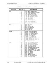
... - CRC ERROR FDD - TIME OUT ERROR FDD - PARITY ERROR RS232C - HDC ERROR HDD - DMA BOUNDARY ERROR FDD - SELECT LINE PRT - OUT OF PAPER PRT - DMA BOUNDARY ERROR HDD - ADDRESS MARK NOT FOUND HDD - BAD COMMAND ERROR HDD - ECC ERROR HDD - BAD COMMAND ERROR FDD - DMA OVERRUN ERROR FDD - TIME OUT PRT - HDC NOT RESET ERROR HDD - SEEK ERROR HDD - ECC RECOVER ENABLE HDD - 3 Tests and Diagnostics 3.18 Error Code and Error Status Names Table 3-2 Error codes and error status names (2/3) Device name FDD Printer ASYNC HDD Error code 01 02...
... - CRC ERROR FDD - TIME OUT ERROR FDD - PARITY ERROR RS232C - HDC ERROR HDD - DMA BOUNDARY ERROR FDD - SELECT LINE PRT - OUT OF PAPER PRT - DMA BOUNDARY ERROR HDD - ADDRESS MARK NOT FOUND HDD - BAD COMMAND ERROR HDD - ECC ERROR HDD - BAD COMMAND ERROR FDD - DMA OVERRUN ERROR FDD - TIME OUT PRT - HDC NOT RESET ERROR HDD - SEEK ERROR HDD - ECC RECOVER ENABLE HDD - 3 Tests and Diagnostics 3.18 Error Code and Error Status Names Table 3-2 Error codes and error status names (2/3) Device name FDD Printer ASYNC HDD Error code 01 02...

Maintenance Manual
Page 161
... SECTOR HDD - ACCESS TIME ERROR HDD - NO HDD HDD - MULTIPLAY ERROR ADDRESS LINE ERROR CE#1 LINE ERROR CE#2 LINE ERROR DATA LINE ERROR WAIT LINE ERROR BSY# LINE ERROR BVD1 LINE ERROR ZV-Port ERROR NO PCMCIA CARD TYPE ERROR ZV_CONT# ERROR BAD COMMAND ILLEGAL LENGTH UNIT ATTENTION MEDIA CHANGE REQUEST MEDIA DETECTED ADDITIMAL SENSE BOUNDARY ERROR CORRECTED DATA ERROR DRIVE NOT READY SEEK ERROR TIME OUT RESET ERROR ADDRESS ERROR PORTEGE R600 Maintenance Manual (960-709) [CONFIDENTIAL] 3-37 3.18 Error Code and Error Status Names 3 Tests and Diagnostics Table 3-2 Error codes...
... SECTOR HDD - ACCESS TIME ERROR HDD - NO HDD HDD - MULTIPLAY ERROR ADDRESS LINE ERROR CE#1 LINE ERROR CE#2 LINE ERROR DATA LINE ERROR WAIT LINE ERROR BSY# LINE ERROR BVD1 LINE ERROR ZV-Port ERROR NO PCMCIA CARD TYPE ERROR ZV_CONT# ERROR BAD COMMAND ILLEGAL LENGTH UNIT ATTENTION MEDIA CHANGE REQUEST MEDIA DETECTED ADDITIMAL SENSE BOUNDARY ERROR CORRECTED DATA ERROR DRIVE NOT READY SEEK ERROR TIME OUT RESET ERROR ADDRESS ERROR PORTEGE R600 Maintenance Manual (960-709) [CONFIDENTIAL] 3-37 3.18 Error Code and Error Status Names 3 Tests and Diagnostics Table 3-2 Error codes...

Maintenance Manual
Page 174
BIOS should be used in WINDOWS, check the product specification. . 3-50 [CONFIDENTIAL] PORTEGE R600 Maintenance Manual (960-709) High Speed SD Card (V1.10 optional) for Normal Speed (max 25MHz) - SD Card (R5C847 Writh/Read) The functional check of SD Card. Classical SD Card (V1.00) for High Speed (max 50MHz) - SDHC (>= 4GB) Supported * SDIO devices are carried out. Intel Kedron is NG, check the error message...
BIOS should be used in WINDOWS, check the product specification. . 3-50 [CONFIDENTIAL] PORTEGE R600 Maintenance Manual (960-709) High Speed SD Card (V1.10 optional) for Normal Speed (max 25MHz) - SD Card (R5C847 Writh/Read) The functional check of SD Card. Classical SD Card (V1.00) for High Speed (max 50MHz) - SDHC (>= 4GB) Supported * SDIO devices are carried out. Intel Kedron is NG, check the error message...

Maintenance Manual
Page 210
... you to set or reset the user password for power on the first page of options displays the computer's memory. Registered Supervisor Password has been registered. HDD password is displayed on . System Date/Time Sets the date and time. 3 Tests and Diagnostics 3.32 SETUP SETUP Options The SETUP screen is automatically calculated by the computer. Not Registered Change or remove the password. (Default) (a) Supervisor Password This setting, which is a security function to the Online Manual. 4. This...
... you to set or reset the user password for power on the first page of options displays the computer's memory. Registered Supervisor Password has been registered. HDD password is displayed on . System Date/Time Sets the date and time. 3 Tests and Diagnostics 3.32 SETUP SETUP Options The SETUP screen is automatically calculated by the computer. Not Registered Change or remove the password. (Default) (a) Supervisor Password This setting, which is a security function to the Online Manual. 4. This...

Maintenance Manual
Page 218
... eSATA connector. Serial ATA Port4 (Default): Enables the eSATA connector When "SATA Controller Mode" is set the power-saving function of Enhanced C-States on the following conditions. 3 Tests and Diagnostics 3.32 SETUP (b) PCI Express Link ASPM This option set as "IDE", it is displayed as "IDE." Enabled This lowers the power consumption. (Default) Disabled This does not lower the power consumption. 9. Auto Disabled Enabled PCI Express devices are not used while battery operation. (Default) Disable the Power-saving function and drive with maximum performance.
... eSATA connector. Serial ATA Port4 (Default): Enables the eSATA connector When "SATA Controller Mode" is set the power-saving function of Enhanced C-States on the following conditions. 3 Tests and Diagnostics 3.32 SETUP (b) PCI Express Link ASPM This option set as "IDE", it is displayed as "IDE." Enabled This lowers the power consumption. (Default) Disabled This does not lower the power consumption. 9. Auto Disabled Enabled PCI Express devices are not used while battery operation. (Default) Disable the Power-saving function and drive with maximum performance.


