User Guide
Page 115
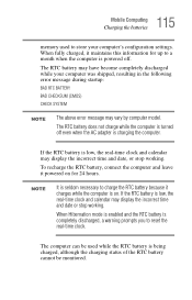
...real-time clock and calendar may have become completely discharged while your computer's configuration settings. The computer can be monitored. If the RTC battery is low, the real-time clock and calendar may vary by computer model. When fully charged, it maintains this information for 24 ... used while the RTC battery is being charged, although the charging status of the RTC battery cannot be used to store your computer was shipped, resulting in the following error message during startup: BAD RTC BATTERY BAD CHECKSUM (CMOS) CHECK SYSTEM NOTE The above error message may display ...
...real-time clock and calendar may have become completely discharged while your computer's configuration settings. The computer can be monitored. If the RTC battery is low, the real-time clock and calendar may vary by computer model. When fully charged, it maintains this information for 24 ... used while the RTC battery is being charged, although the charging status of the RTC battery cannot be used to store your computer was shipped, resulting in the following error message during startup: BAD RTC BATTERY BAD CHECKSUM (CMOS) CHECK SYSTEM NOTE The above error message may display ...

Maintenance Manual
Page 17
...buttons on the model, one port of up to the computer can be connected. 1-2 PORTEGE M100 Maintenance Manual (960-452) q Batteries The computer has two batteries: a lithium-ion main battery pack and RTC battery (that uses a 101- One module must be installed in Microsoft Windows XP. q ...mounted. or 102-key enhanced keyboard. It is compatible with Fast InfraRed (FIR) standards enabling wireless up the Real Time Clock and CMOS memory). memory modules. The USB enables daisy-chain connection of IEEE1394 connector is attached in the slim select bay. 1 Hardware Overview...
...buttons on the model, one port of up to the computer can be connected. 1-2 PORTEGE M100 Maintenance Manual (960-452) q Batteries The computer has two batteries: a lithium-ion main battery pack and RTC battery (that uses a 101- One module must be installed in Microsoft Windows XP. q ...mounted. or 102-key enhanced keyboard. It is compatible with Fast InfraRed (FIR) standards enabling wireless up the Real Time Clock and CMOS memory). memory modules. The USB enables daisy-chain connection of IEEE1394 connector is attached in the slim select bay. 1 Hardware Overview...

Maintenance Manual
Page 60
If you press the F1 key as the message instructs. Then press [F1] key (c)*** RTC battery is low or CMOS checksum is shown on the display, perform Check 1. The IRT tests each IC on the system board and initializes it. q If an error message is ... on, the system performs the Initial Reliability Test (IRT) installed in the RTC memory (CMOS type memory) is not the same as the actual configuration or when the data is lost. Then press [F1] key 2-18 PORTEGE M100 Maintenance Manual (960-452) These errors occur, when the system configuration preserved in the BIOS...
If you press the F1 key as the message instructs. Then press [F1] key (c)*** RTC battery is low or CMOS checksum is shown on the display, perform Check 1. The IRT tests each IC on the system board and initializes it. q If an error message is ... on, the system performs the Initial Reliability Test (IRT) installed in the RTC memory (CMOS type memory) is not the same as the actual configuration or when the data is lost. Then press [F1] key 2-18 PORTEGE M100 Maintenance Manual (960-452) These errors occur, when the system configuration preserved in the BIOS...

Maintenance Manual
Page 61
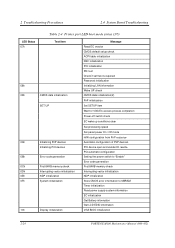
... (20) displays, go to the FDD Troubleshooting Procedures in Section 2.5. (1) PIT ERROR (2) MEMORY REFRESH ERROR (3) TIMER CH.2 OUT ERROR (4) CMOS CHECKSUM ERROR (5) CMOS BAD BATTERY ERROR (6) FIRST 64KB MEMORY ERROR (7) FIRST 64KB MEMORY PARITY ERROR (8) VRAM ERROR (9) SYSTEM MEMORY ERROR (10) SYSTEM MEMORY PARITY ERROR (11...20) IDE #0 ERROR (21) IDE #1 ERROR (22) NO FDD ERROR (23) FDC ERROR (24) TIMER INTERRUPT ERROR (25) RTC UPDATE ERROR PORTEGE M100 Maintenance Manual (960-452) 2-19 If one of the following error messages (1) through (17), (24) or (25) displays, go to the Keyboard ...
... (20) displays, go to the FDD Troubleshooting Procedures in Section 2.5. (1) PIT ERROR (2) MEMORY REFRESH ERROR (3) TIMER CH.2 OUT ERROR (4) CMOS CHECKSUM ERROR (5) CMOS BAD BATTERY ERROR (6) FIRST 64KB MEMORY ERROR (7) FIRST 64KB MEMORY PARITY ERROR (8) VRAM ERROR (9) SYSTEM MEMORY ERROR (10) SYSTEM MEMORY PARITY ERROR (11...20) IDE #0 ERROR (21) IDE #1 ERROR (22) NO FDD ERROR (23) FDC ERROR (24) TIMER INTERRUPT ERROR (25) RTC UPDATE ERROR PORTEGE M100 Maintenance Manual (960-452) 2-19 If one of the following error messages (1) through (17), (24) or (25) displays, go to the Keyboard ...

Maintenance Manual
Page 65
...Test item BIOS rewriting check 00h IRT Check system 01h Memory check SM-RAM stack area test 02h CMOS check and initialization 03h Resume branch 04h SMRAM initialization 05h Storage of CPU state map 06h Advance processing...and size check SM-RAM stack area test Enabling L1 cache CMOS access test CMOS battery level check CMOS checksum CMOS data initialization (1) Set IRT status DRAM size storing in CMOS Resume branch check SM-RAM checksum SMI control flag clear System... tate map Setting of device necessary before initializing of PCI bus PORTEGE M100 Maintenance Manual (960-452) 2-23
...Test item BIOS rewriting check 00h IRT Check system 01h Memory check SM-RAM stack area test 02h CMOS check and initialization 03h Resume branch 04h SMRAM initialization 05h Storage of CPU state map 06h Advance processing...and size check SM-RAM stack area test Enabling L1 cache CMOS access test CMOS battery level check CMOS checksum CMOS data initialization (1) Set IRT status DRAM size storing in CMOS Resume branch check SM-RAM checksum SMI control flag clear System... tate map Setting of device necessary before initializing of PCI bus PORTEGE M100 Maintenance Manual (960-452) 2-23
Maintenance Manual
Page 66
... check 0Dh Interrupting vector initialization 0Eh NDP initialization 0Fh System initialization 10h Display initialization Message Read EC version CMOS default setup check ACPI table initialization KBC initialization PCI initialization PIC test Check if self test is required... First 64KB memory check Interrupting vector initialization NDP initialization Store CMOS error information to SMRAM Timer initialization Read power supply system information EC initialization Get Battery information Get LCD EDID information VGA BIOS initialization 2-24 PORTEGE M100 Maintenance Manual (960-452)
... check 0Dh Interrupting vector initialization 0Eh NDP initialization 0Fh System initialization 10h Display initialization Message Read EC version CMOS default setup check ACPI table initialization KBC initialization PCI initialization PIC test Check if self test is required... First 64KB memory check Interrupting vector initialization NDP initialization Store CMOS error information to SMRAM Timer initialization Read power supply system information EC initialization Get Battery information Get LCD EDID information VGA BIOS initialization 2-24 PORTEGE M100 Maintenance Manual (960-452)

Maintenance Manual
Page 68
... save / restore) Set font address for resume password Set USB/KB repeat parameter T shadow RAM size store Extended memory store in CMOS System source update DMI table update INT 15h E820h function memory map rewrite DMI wake up update and SM-BIOS structure table update ACPI...BIOS TIT checksum Runtime IRT flag clear Runtime checksum update Hibernation branch CPU, HDD upgrade check Set battery save mode Set date Close PCI device configuration area Cache control Wait for serial port initialization completion Runtime checksum update Set thermal duty 2-26 PORTEGE M100 Maintenance Manual (960-452)
... save / restore) Set font address for resume password Set USB/KB repeat parameter T shadow RAM size store Extended memory store in CMOS System source update DMI table update INT 15h E820h function memory map rewrite DMI wake up update and SM-BIOS structure table update ACPI...BIOS TIT checksum Runtime IRT flag clear Runtime checksum update Hibernation branch CPU, HDD upgrade check Set battery save mode Set date Close PCI device configuration area Cache control Wait for serial port initialization completion Runtime checksum update Set thermal duty 2-26 PORTEGE M100 Maintenance Manual (960-452)
User Manual
Page 122
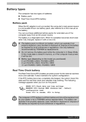
...short even when fully charged, replace it will be replaced only by your dealer or by a TOSHIBA service representative. WARNING 0251:System CMOS checksum bad - The battery can explode if not properly replaced, used . In this data and the real time clock ...battery. The battery is a lithium battery and should be lost. ■ Battery type (depending on the model you turn on the power: ERROR 0271:Check date and time settings. Power and Power-Up Modes Battery types The computer has two types of the battery as required by local ordinances or regulations. 6-4 Satellite M100...
...short even when fully charged, replace it will be replaced only by your dealer or by a TOSHIBA service representative. WARNING 0251:System CMOS checksum bad - The battery can explode if not properly replaced, used . In this data and the real time clock ...battery. The battery is a lithium battery and should be lost. ■ Battery type (depending on the model you turn on the power: ERROR 0271:Check date and time settings. Power and Power-Up Modes Battery types The computer has two types of the battery as required by local ordinances or regulations. 6-4 Satellite M100...
User Manual
Page 176
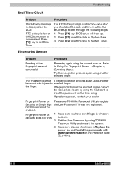
...sure you should set Date/ Time. Set the User Password by using another enrolled finger. Fingerprint Power on the LCD: RTC battery is low or CMOS checksum is inconsistent. BIOS setup will boot up. 2. The fingerprint cannot Try the recognition process again using the keyboard to set...the fingerprint reader on the Protector Suite QL setting. 9-18 Satellite M100 Press [F2] key to input the password for the time being. Please try again using TOSHIBA Password Utility and restart the system. 3. The RTC battery charge has become exhausted, you have enroll finger in within the...
...sure you should set Date/ Time. Set the User Password by using another enrolled finger. Fingerprint Power on the LCD: RTC battery is low or CMOS checksum is inconsistent. BIOS setup will boot up. 2. The fingerprint cannot Try the recognition process again using the keyboard to set...the fingerprint reader on the Protector Suite QL setting. 9-18 Satellite M100 Press [F2] key to input the password for the time being. Please try again using TOSHIBA Password Utility and restart the system. 3. The RTC battery charge has become exhausted, you have enroll finger in within the...


