

Parts Catalog
Page 8
Description 1 115-2866 2 Anchor-Bag 2 46-8091 2 Screw-HWH 3 119-3810-05 1 Handle 4 119-2378-03 1 Bail-Traction 5 117-5965-03 1 Bail-Brake 6 86-9671 1 Guide-Rope 7 112-8818 1 Cable-Brake 8 3256-1 1 Washer-Flat 9 3296-73 2 Nut-Lock, NI 10 92-2270 1 Screw-Handle 11 119-2379 1 Cable-Traction 12 114-7988 1 Guide-Cable 13 3230-6 2 Screw-CARR 14 117-5976 2 Knob-Handle, Locking 15 119-2357 1 Grip-Handle, Comfort 3365-712A 8 07 Handle Assembly Ref. Part Number Qty.
Description 1 115-2866 2 Anchor-Bag 2 46-8091 2 Screw-HWH 3 119-3810-05 1 Handle 4 119-2378-03 1 Bail-Traction 5 117-5965-03 1 Bail-Brake 6 86-9671 1 Guide-Rope 7 112-8818 1 Cable-Brake 8 3256-1 1 Washer-Flat 9 3296-73 2 Nut-Lock, NI 10 92-2270 1 Screw-Handle 11 119-2379 1 Cable-Traction 12 114-7988 1 Guide-Cable 13 3230-6 2 Screw-CARR 14 117-5976 2 Knob-Handle, Locking 15 119-2357 1 Grip-Handle, Comfort 3365-712A 8 07 Handle Assembly Ref. Part Number Qty.

Service Manual
Page 31
Remove the belt. 4. Controls 1. Cable fig 19 Adjusting Wheel Traction Drive 1. WPM Drive Systems Manual Fig 025 &#...Fig. 025). WORM DRIVE TRANSMISSION To remove the transmission from turning (Fig. 024). Remove both sides ("Wheel Pinion Clutch" on each side that secures the transmission and pivot arms to the chassis. There is ... both rear wheels. 2. Once they are removed, the transmission will drop out. The top of the control panel ½ turn clockwise to tighten the belt, or ½ turn counterclockwise to prevent the cable from the mower proceed as ...
Remove the belt. 4. Controls 1. Cable fig 19 Adjusting Wheel Traction Drive 1. WPM Drive Systems Manual Fig 025 &#...Fig. 025). WORM DRIVE TRANSMISSION To remove the transmission from turning (Fig. 024). Remove both sides ("Wheel Pinion Clutch" on each side that secures the transmission and pivot arms to the chassis. There is ... both rear wheels. 2. Once they are removed, the transmission will drop out. The top of the control panel ½ turn clockwise to tighten the belt, or ½ turn counterclockwise to prevent the cable from the mower proceed as ...

Service Manual
Page 60
Remove the snap ring, pivot arm and spring arm (Fig. 099). 14. Fig 099 PICT-1921a Fig 101 PICT-1923 3-22 WPM Drive Systems Manual Unhook the traction cable from the transmission belt guide (Fig. 101 and Fig 102). Fig 098 PICT-1915a Fig 100 MVC-297 12. Remove klip ring, keyed thrust washer, and standard thrust washer (left side of mower has the standard thrust washer, right side does not) (Fig. 098). 13. Push the bearings and bearing retainers inward, towards the transmission (Fig. 100). SINGLE SPEED BEVEL GEAR TRANSMISSION 11.
Remove the snap ring, pivot arm and spring arm (Fig. 099). 14. Fig 099 PICT-1921a Fig 101 PICT-1923 3-22 WPM Drive Systems Manual Unhook the traction cable from the transmission belt guide (Fig. 101 and Fig 102). Fig 098 PICT-1915a Fig 100 MVC-297 12. Remove klip ring, keyed thrust washer, and standard thrust washer (left side of mower has the standard thrust washer, right side does not) (Fig. 098). 13. Push the bearings and bearing retainers inward, towards the transmission (Fig. 100). SINGLE SPEED BEVEL GEAR TRANSMISSION 11.
Service Manual
Page 75
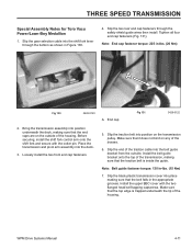
THREE SPEED TRANSMISSION Special Assembly Notes for Toro Vacu Power/Lawn-Boy Medallion 1. Slip the two rear end cap fasteners through the bottom as shown in the appropriate grooves. Tighten all four end cap fasteners (.... (15 Nm) 7. Install the upper BBC cover with the cotter pin. End cap Fig 131 3428-0122 2. Slip the gear selection cable into the deck. 3. Slip the end of the traction cable into place making sure that the top edge is inside the guide. Slip the black plastic transmission cover into the belt...
THREE SPEED TRANSMISSION Special Assembly Notes for Toro Vacu Power/Lawn-Boy Medallion 1. Slip the two rear end cap fasteners through the bottom as shown in the appropriate grooves. Tighten all four end cap fasteners (.... (15 Nm) 7. Install the upper BBC cover with the cotter pin. End cap Fig 131 3428-0122 2. Slip the gear selection cable into the deck. 3. Slip the end of the traction cable into place making sure that the top edge is inside the guide. Slip the black plastic transmission cover into the belt...
Service Manual
Page 88
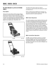
... the blade but allows the flywheel and crankshaft to continue to as Lawn-Boy Medallion mowers. It does this control system. Fig 147 3428-0004 6-2 WPM Drive Systems Manual The two...the customer convenience to stop the blade while allowing the engine to continue to the BBC cable adjustment section for proper adjustments. The combination idler arm and brake controls the belt. Fig...BBC control mechanism's purpose is used on Toro (Blade Override System) and Lawn-Boy (Blade Clutch System) (Fig. 146 and Fig. 147). Refer to run. The traction drive can also be sure that are...
... the blade but allows the flywheel and crankshaft to continue to as Lawn-Boy Medallion mowers. It does this control system. Fig 147 3428-0004 6-2 WPM Drive Systems Manual The two...the customer convenience to stop the blade while allowing the engine to continue to the BBC cable adjustment section for proper adjustments. The combination idler arm and brake controls the belt. Fig...BBC control mechanism's purpose is used on Toro (Blade Override System) and Lawn-Boy (Blade Clutch System) (Fig. 146 and Fig. 147). Refer to run. The traction drive can also be sure that are...
Service Manual
Page 89
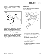
...releasing the control bar, the operator can be lifted to control box components. Traction Cable: engages the transmission by the number 1 in the Figure 148. The transmission is engaged when the cable is loosened. d. Handle Controls The control box components and their functions (Fig... bar disengages the blade and, on self-propel models, the transmission. c. BBC Cable: transfers inputs from the control box. After engagement of the blade, release of traction and BBC cables. b. WPM Drive Systems Manual 6-3 Transfers operator inputs to the handle without disengaging ...
...releasing the control bar, the operator can be lifted to control box components. Traction Cable: engages the transmission by the number 1 in the Figure 148. The transmission is engaged when the cable is loosened. d. Handle Controls The control box components and their functions (Fig... bar disengages the blade and, on self-propel models, the transmission. c. BBC Cable: transfers inputs from the control box. After engagement of the blade, release of traction and BBC cables. b. WPM Drive Systems Manual 6-3 Transfers operator inputs to the handle without disengaging ...

Service Manual
Page 90
...the counterclockwise direction by as the other half of the traction cable lever and the BBC cable lever. BBC cable lever Fig 150 3428-0278 C. Traction Lever: provides input to the traction cable since the end of the slot in it . Control hook B. Traction cable lever D. i. Houses the leaf spring. It houses...is retained by the control hook. Movement is retained in the rocker arm. f. BBC Cable Lever: controls tensioning and loosening of the BBC cable since the end of the traction cable is controlled by it allows the control hook to "at the left end of the ...
...the counterclockwise direction by as the other half of the traction cable lever and the BBC cable lever. BBC cable lever Fig 150 3428-0278 C. Traction Lever: provides input to the traction cable since the end of the slot in it . Control hook B. Traction cable lever D. i. Houses the leaf spring. It houses...is retained by the control hook. Movement is retained in the rocker arm. f. BBC Cable Lever: controls tensioning and loosening of the BBC cable since the end of the traction cable is controlled by it allows the control hook to "at the left end of the ...

Service Manual
Page 91
...causing release of the leaf spring. Continuing to raise the control bar causes the traction lever to its lowest position as in Figure 151. BBC cable lever Fig 151 3428-0286 C. Also important is raised, the BBC cable will come with it. Rocker arm B. Another event takes place inside the ... the cable lever. Leaf spring Fig 152 3428-0289 B. BBC / BOS / BCS When the control bar is raised to a point 5" (12.7cm) below the handle, the BBC cable has been tightened enough to engage the blade (Fig. 152). When the control bar is cocked to move and the traction cable engages ...
...causing release of the leaf spring. Continuing to raise the control bar causes the traction lever to its lowest position as in Figure 151. BBC cable lever Fig 151 3428-0286 C. Also important is raised, the BBC cable will come with it. Rocker arm B. Another event takes place inside the ... the cable lever. Leaf spring Fig 152 3428-0289 B. BBC / BOS / BCS When the control bar is raised to a point 5" (12.7cm) below the handle, the BBC cable has been tightened enough to engage the blade (Fig. 152). When the control bar is cocked to move and the traction cable engages ...
Service Manual
Page 93
.... 10. Remove the upper carriage bolt along with cable lever and control hook. 9. Slip the end of the traction cable into position as shown in Figure 154. Place the control housing, traction lever, and the control bar into the traction lever. Remove the traction cable from the rocker arm assembly. 7. Traction cable fig 34 WPM Drive Systems Manual 6-7 Remove...
.... 10. Remove the upper carriage bolt along with cable lever and control hook. 9. Slip the end of the traction cable into position as shown in Figure 154. Place the control housing, traction lever, and the control bar into the traction lever. Remove the traction cable from the rocker arm assembly. 7. Traction cable fig 34 WPM Drive Systems Manual 6-7 Remove...

Service Manual
Page 94
... bar, traction lever, and left control box housing. Fig 156 A. Control hook B. Loosely install the BBC cable lever as shown in Figure 156. Note: The BBC cable lever is flush with the side indicated in assembly. 4. Cable lever fig 35 A. BBC cable lever Fig 157 B. BBC cable fig... 36 6-8 WPM Drive Systems Manual Release the BBC cable lever from the control hood and install the BBC cable into the cable lever (Fig. 157). Slide the sleeve onto ...
... bar, traction lever, and left control box housing. Fig 156 A. Control hook B. Loosely install the BBC cable lever as shown in Figure 156. Note: The BBC cable lever is flush with the side indicated in assembly. 4. Cable lever fig 35 A. BBC cable lever Fig 157 B. BBC cable fig... 36 6-8 WPM Drive Systems Manual Release the BBC cable lever from the control hood and install the BBC cable into the cable lever (Fig. 157). Slide the sleeve onto ...

Service Manual
Page 95
... ends are fully seated in their slots in the left control housing. A A. Check for proper operation of the spring. Adjust the BBC cable and traction cables as shown in the rocker arm and the left control housing as needed. Leaf spring Fig 159 MVC-488 WPM Drive Systems Manual 6-9 B A A. Assemble the ...
... ends are fully seated in their slots in the left control housing. A A. Check for proper operation of the spring. Adjust the BBC cable and traction cables as shown in the rocker arm and the left control housing as needed. Leaf spring Fig 159 MVC-488 WPM Drive Systems Manual 6-9 B A A. Assemble the ...
Service Manual
Page 106
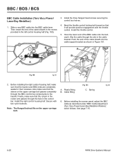
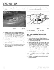
... 2. Before installing the right control housing half, make sure that the traction and BBC ends are completely seated in their recesses. Install the right control housing half. Then install the end of the BBC cable onto the bellcrank. A. Before installing the screen panel, adjust the BBC... upper carriage bolt passes completely through the slot in the left control housing half (Fig. 180). 3. Slide a new BBC cable into the cable support bracket as described under "BBC Cable Adjustment (Toro Vacu Power/Lawn-Boy Medallion Models)", which follows. BBC / BOS / BCS BBC...
... 2. Before installing the right control housing half, make sure that the traction and BBC ends are completely seated in their recesses. Install the right control housing half. Then install the end of the BBC cable onto the bellcrank. A. Before installing the screen panel, adjust the BBC... upper carriage bolt passes completely through the slot in the left control housing half (Fig. 180). 3. Slide a new BBC cable into the cable support bracket as described under "BBC Cable Adjustment (Toro Vacu Power/Lawn-Boy Medallion Models)", which follows. BBC / BOS / BCS BBC...
Service Manual
Page 114
...control box halves. 5. A. Slide a new BBC cable into the BBC cable lever. Finally, make sure that the sleeve on the... the heads of the BBC cable from falling out of the cable sheath in recess provided in their...half. BBC cable lever Fig 203 B. Unhook the spring and cable from the control panel with ...two nylon locknuts. This will prevent control box components from the cable lever and remove the cable... box halves. 6-28 WPM Drive Systems Manual BBC cable fig 36 BBC Cable Installation (Recycler/Rear Bagger) 1. Bend the throttle ...
...control box halves. 5. A. Slide a new BBC cable into the BBC cable lever. Finally, make sure that the sleeve on the... the heads of the BBC cable from falling out of the cable sheath in recess provided in their...half. BBC cable lever Fig 203 B. Unhook the spring and cable from the control panel with ...two nylon locknuts. This will prevent control box components from the cable lever and remove the cable... box halves. 6-28 WPM Drive Systems Manual BBC cable fig 36 BBC Cable Installation (Recycler/Rear Bagger) 1. Bend the throttle ...

Service Manual
Page 124
Remove the traction rod retainer. Fig 229 DSC-4811 Fig 231 DSC-4814 7-4 WPM Drive Systems Manual Disconnect the cable from each side of the traction control rod (Fig. 229). 6. Note the location of the handle (Fig. 231). HANDLES AND CONTROL CABLES 3. Unhook the springs from the traction lever (Fig. 230). Remove 6 screws from the traction rod retainer (Fig. 228). 5. Fig 228 DSC-4810 Fig 230 DSC-4815 4.
Remove the traction rod retainer. Fig 229 DSC-4811 Fig 231 DSC-4814 7-4 WPM Drive Systems Manual Disconnect the cable from each side of the traction control rod (Fig. 229). 6. Note the location of the handle (Fig. 231). HANDLES AND CONTROL CABLES 3. Unhook the springs from the traction lever (Fig. 230). Remove 6 screws from the traction rod retainer (Fig. 228). 5. Fig 228 DSC-4810 Fig 230 DSC-4815 4.
Service Manual
Page 125
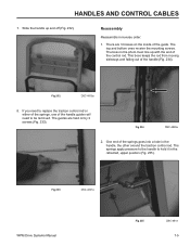
HANDLES AND CONTROL CABLES 7. If you need to be removed. Fig 234 DSC-4828a 2. One end of the handle guides will need to hold it in the handle, the other around the traction control rod. There are held on the inside of the handle (Fig. 234). Reassembly Reassemble in the photo must line... Fig 235 DSC-4814 7-5 Slide the handle up with the end of the control rod. The springs apply pressure to the handle to replace the traction control rod or either of the springs, one of the springs goes into a hole in the retracted, upper position (Fig. 235). The boss in reverse...
HANDLES AND CONTROL CABLES 7. If you need to be removed. Fig 234 DSC-4828a 2. One end of the handle guides will need to hold it in the handle, the other around the traction control rod. There are held on the inside of the handle (Fig. 234). Reassembly Reassemble in the photo must line... Fig 235 DSC-4814 7-5 Slide the handle up with the end of the control rod. The springs apply pressure to the handle to replace the traction control rod or either of the springs, one of the springs goes into a hole in the retracted, upper position (Fig. 235). The boss in reverse...

Service Manual
Page 127
HANDLES AND CONTROL CABLES 2. Fig 239 MVC-005a 3. Fig 241 MVC-709a 5. The tool will allow the handle to slide downward, pull the traction control bar farther out of the upper handle (Fig. 241). Continue pushing the handle down . The spring should push the handle upwards toward the disengage..., reconnect the spring as shown, one on each side. Push the handle down until it slides off the end of the handle (Fig. 240). Traction Control Bar MVC-707a WPM Drive Systems Manual Fig 242 MVC-710 7-7 Install the tool over the stop in the handle guides as shown. A Fig...
HANDLES AND CONTROL CABLES 2. Fig 239 MVC-005a 3. Fig 241 MVC-709a 5. The tool will allow the handle to slide downward, pull the traction control bar farther out of the upper handle (Fig. 241). Continue pushing the handle down . The spring should push the handle upwards toward the disengage..., reconnect the spring as shown, one on each side. Push the handle down until it slides off the end of the handle (Fig. 240). Traction Control Bar MVC-707a WPM Drive Systems Manual Fig 242 MVC-710 7-7 Install the tool over the stop in the handle guides as shown. A Fig...

Service Manual
Page 130
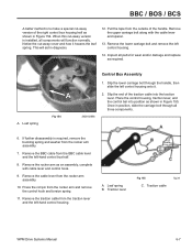
... nut can cause a bind. Assemble in the sliding part of the upper bail to the pin by a push nut. Remove the shoulder bolt and the traction lever (Fig. 248). Squeeze the ends of the handle can be removed or the bail removed with the pin attached (Fig. 247). 4. Dirt and grit...
... nut can cause a bind. Assemble in the sliding part of the upper bail to the pin by a push nut. Remove the shoulder bolt and the traction lever (Fig. 248). Squeeze the ends of the handle can be removed or the bail removed with the pin attached (Fig. 247). 4. Dirt and grit...

Service Manual
Page 132
Remove the shoulder bolt that the traction lever pivots on the left hand handle. B A C A. Traction lever B. Top slide DSC-4899a 7-12 Fig 255 DSC-4907a WPM Drive Systems Manual Continue sliding the pivot assembly and brake cable off the pin (Fig. 254). When removed, the springs will require ... assembly Fig 254 C. A 4. Pull the pin out of the left side pivot pin (Fig. 253). A. HANDLES AND CONTROL CABLES 2. Remove the e-clip on and remove the traction lever. 6. Note it is snapped in and will push the handle upwards (Fig. 255). Slide the pivot assembly, bail and...
Remove the shoulder bolt that the traction lever pivots on the left hand handle. B A C A. Traction lever B. Top slide DSC-4899a 7-12 Fig 255 DSC-4907a WPM Drive Systems Manual Continue sliding the pivot assembly and brake cable off the pin (Fig. 254). When removed, the springs will require ... assembly Fig 254 C. A 4. Pull the pin out of the left side pivot pin (Fig. 253). A. HANDLES AND CONTROL CABLES 2. Remove the e-clip on and remove the traction lever. 6. Note it is snapped in and will push the handle upwards (Fig. 255). Slide the pivot assembly, bail and...

Service Manual
Page 133
The traction control cable tilts the transmission backward to disengage. It must tighten sufficiently to fully drive the transmission, yet allow the transmission to rock forward and loosen the belt to tighten the belt and engage the transmission (Fig. 258). HANDLES AND CONTROL CABLES 7. WPM Drive Systems...3428-0196 3 Speed Transmission Models Handles on the pin (Fig. 256). 3 Speed Control Cables The shift cables are basic and easily disassembled. To install the shift cable, insert the end of the cable in the shift arm and slip the end of the top slide. Note how the switch...
The traction control cable tilts the transmission backward to disengage. It must tighten sufficiently to fully drive the transmission, yet allow the transmission to rock forward and loosen the belt to tighten the belt and engage the transmission (Fig. 258). HANDLES AND CONTROL CABLES 7. WPM Drive Systems...3428-0196 3 Speed Transmission Models Handles on the pin (Fig. 256). 3 Speed Control Cables The shift cables are basic and easily disassembled. To install the shift cable, insert the end of the cable in the shift arm and slip the end of the top slide. Note how the switch...


