Installation Manual
Page 2
...thermador.com We look forward to hearing from you to the appliance or property may occur as a result of this advisory. NOTICE: This indicates that minor or moderate injuries may occur as a result of non-observance of non-compliance with this warning. Table of Contents Safety 1 Installation 2 Step 1: EXHAUST-AIR MODE 2 Step 2: PREPARING THE WALL... 2 Step 3: INSTALLATION 3 Wire Diagram 5 Customer Support, Accessories & Parts back page Safety Definitions 9 WARNING This...
...thermador.com We look forward to hearing from you to the appliance or property may occur as a result of this advisory. NOTICE: This indicates that minor or moderate injuries may occur as a result of non-observance of non-compliance with this warning. Table of Contents Safety 1 Installation 2 Step 1: EXHAUST-AIR MODE 2 Step 2: PREPARING THE WALL... 2 Step 3: INSTALLATION 3 Wire Diagram 5 Customer Support, Accessories & Parts back page Safety Definitions 9 WARNING This...
Installation Manual
Page 3
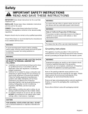
... for the owner. INSTALLER: Please leave these Installation Instructions with this blower with packaging material. DO NOT vent exhaust air into wall or ceiling, do not use to prevent the power from being switched on accidentally. Remove all tape and packaging before installing, switch power off at the service panel and lock the panel to exhaust hazardous or explosive materials and vapors. English 1 WARNING To avoid electrical shock hazard, before using the appliance...
... for the owner. INSTALLER: Please leave these Installation Instructions with this blower with packaging material. DO NOT vent exhaust air into wall or ceiling, do not use to prevent the power from being switched on accidentally. Remove all tape and packaging before installing, switch power off at the service panel and lock the panel to exhaust hazardous or explosive materials and vapors. English 1 WARNING To avoid electrical shock hazard, before using the appliance...
Installation Manual
Page 4
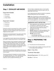
... chimney (such as gas, oil or coal-fired heaters, continuous-flow heaters, hot-water boilers), care must be discharged in accordance with downdraft systems. • DO NOT install the blower - Weight: 17.8 kg / 39 lbs Technical Information Electrical Requirements: 120 V; 60 Hz, max. 8.5 A Duct Size: 10" (254 mm) English 2 Exhaust air must be taken to the extractor hood except when used for ventilating rooms in which stoves...
... chimney (such as gas, oil or coal-fired heaters, continuous-flow heaters, hot-water boilers), care must be discharged in accordance with downdraft systems. • DO NOT install the blower - Weight: 17.8 kg / 39 lbs Technical Information Electrical Requirements: 120 V; 60 Hz, max. 8.5 A Duct Size: 10" (254 mm) English 2 Exhaust air must be taken to the extractor hood except when used for ventilating rooms in which stoves...
Installation Manual
Page 5
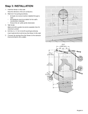
... • At least one screw must be installed through a stud. • All hardware must be suitable for electrical conduit. 4. Connect the ducting from the blower to the extractor hood and feed to the wall. 5. Drill the 4 x ¼'' (6,3 mm) Ø mounting boreholes. min. 40" (... 3 Note the direction of the air conduction. 2. Insert wall anchors and screw the blower to the outside. Wall break: Mark and drill a guide hole and a separate hole for the wall's construction materials. • Ensure the air outlet points downward. 3. Step 3: INSTALLATION 1. Hold the blower on the...
... • At least one screw must be installed through a stud. • All hardware must be suitable for electrical conduit. 4. Connect the ducting from the blower to the extractor hood and feed to the wall. 5. Drill the 4 x ¼'' (6,3 mm) Ø mounting boreholes. min. 40" (... 3 Note the direction of the air conduction. 2. Insert wall anchors and screw the blower to the outside. Wall break: Mark and drill a guide hole and a separate hole for the wall's construction materials. • Ensure the air outlet points downward. 3. Step 3: INSTALLATION 1. Hold the blower on the...
Installation Manual
Page 6
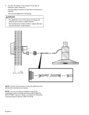
...: Confirm that the blower is securely attached to the extractor hood with a roof plate accessory (RFPLT600P or RFPLT1000P). Connect the blower to the wall and all connections are secure. Use the added connector to hard-wire to the blower, if required. NOTE: The unit can also be isolated, capped with wire nuts and stored in combination with an extension cable if required. Ask your retailer or contact the Thermador Customer Service Team at...
...: Confirm that the blower is securely attached to the extractor hood with a roof plate accessory (RFPLT600P or RFPLT1000P). Connect the blower to the wall and all connections are secure. Use the added connector to hard-wire to the blower, if required. NOTE: The unit can also be isolated, capped with wire nuts and stored in combination with an extension cable if required. Ask your retailer or contact the Thermador Customer Service Team at...

Installation Manual
Page 7
Wire Diagram speed 1 speed 2 speed 3 speed 4 N PE (red) (blue) (orange) (brown) (white) (green/yellow) NOTE: If using a three speed hood, connect speed 1 (red) , speed 2 (blue) and speed 4 (brown). Cap off speed 3 (orange). English 5
Wire Diagram speed 1 speed 2 speed 3 speed 4 N PE (red) (blue) (orange) (brown) (white) (green/yellow) NOTE: If using a three speed hood, connect speed 1 (red) , speed 2 (blue) and speed 4 (brown). Cap off speed 3 (orange). English 5


