Installation Manual
Page 2
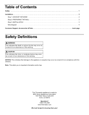
...THE WALL 2 Step 3: INSTALLATION 3 Wire Diagram 5 Customer Support, Accessories & Parts back page Safety Definitions 9 WARNING This indicates that death or serious injuries may occur as a result of non-observance of this warning. 9 CAUTION This indicates that damage to important information and/or tips. This Thermador appliance is made by ...BSH Home Appliances Corporation 1901 Main Street, Suite 600 Irvine, CA 92614 Questions? 1-800-735-4328 www.thermador.com We look forward to hearing from you to the appliance or property may occur as a result of this advisory. Note: This...
...THE WALL 2 Step 3: INSTALLATION 3 Wire Diagram 5 Customer Support, Accessories & Parts back page Safety Definitions 9 WARNING This indicates that death or serious injuries may occur as a result of non-observance of this warning. 9 CAUTION This indicates that damage to important information and/or tips. This Thermador appliance is made by ...BSH Home Appliances Corporation 1901 Main Street, Suite 600 Irvine, CA 92614 Questions? 1-800-735-4328 www.thermador.com We look forward to hearing from you to the appliance or property may occur as a result of this advisory. Note: This...
Installation Manual
Page 3
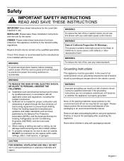
... in accordance with the hood. Safety IMPORTANT SAFETY INSTRUCTIONS READ AND SAVE THESE INSTRUCTIONS IMPORTANT: Save these Instructions for the owner. INSTALLER: Please leave these instructions for proper combustion and exhausting of gases through the flue (chimney) of fire or electric shock, do... before using the appliance. WARNING TO REDUCE THE RISK OF FIRE, ELECTRIC SHOCK, OR INJURY TO PERSONS, OBSERVE THE FOLLOWING: a) Installation work and electrical wiring must be sure to be carried out by the manufacturer to duct air outside. b) Sufficient air is recommended ...
... in accordance with the hood. Safety IMPORTANT SAFETY INSTRUCTIONS READ AND SAVE THESE INSTRUCTIONS IMPORTANT: Save these Instructions for the owner. INSTALLER: Please leave these instructions for proper combustion and exhausting of gases through the flue (chimney) of fire or electric shock, do... before using the appliance. WARNING TO REDUCE THE RISK OF FIRE, ELECTRIC SHOCK, OR INJURY TO PERSONS, OBSERVE THE FOLLOWING: a) Installation work and electrical wiring must be sure to be carried out by the manufacturer to duct air outside. b) Sufficient air is recommended ...
Installation Manual
Page 4
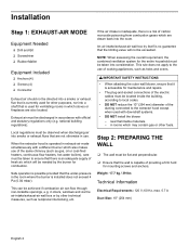
...heaters, hot-water boilers), care must be discharged in the room where the burner is installed does not exceed 4 Pa (0.04 mbar). Step 2: PREPARING THE WALL 䙚 The wall must be taken into consideration. Installation Step 1: EXHAUST-AIR MODE Equipment Needed 䙚 Drill and Bit 䙚 Screwdriver &#...smoke or exhaust flue that is currently used for other purposes, nor into a shaft that is used with downdraft systems. • DO NOT install the blower - Safe operation is possible provided that the wall is capable of fresh air, which are also located. NOTE: When assessing the ...
...heaters, hot-water boilers), care must be discharged in the room where the burner is installed does not exceed 4 Pa (0.04 mbar). Step 2: PREPARING THE WALL 䙚 The wall must be taken into consideration. Installation Step 1: EXHAUST-AIR MODE Equipment Needed 䙚 Drill and Bit 䙚 Screwdriver &#...smoke or exhaust flue that is currently used for other purposes, nor into a shaft that is used with downdraft systems. • DO NOT install the blower - Safe operation is possible provided that the wall is capable of fresh air, which are also located. NOTE: When assessing the ...
Installation Manual
Page 5
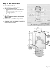
... conduction. 2. Drill the 4 x ¼'' (6,3 mm) Ø mounting boreholes. Hold the blower on the wall. Mark the 4 mounting boreholes. • At least one screw must be installed through a stud. • All hardware must be suitable for electrical conduit. 4. Connect the ducting from the blower to the extractor hood and feed to the..." (148 mm) ¾" (19 mm) 7 3/16" (183 mm) 15½" (394 mm) 6 5/16" (160 mm) 13/16" (21 mm) 21¼" (540 mm) English 3 Step 3: INSTALLATION 1.
... conduction. 2. Drill the 4 x ¼'' (6,3 mm) Ø mounting boreholes. Hold the blower on the wall. Mark the 4 mounting boreholes. • At least one screw must be installed through a stud. • All hardware must be suitable for electrical conduit. 4. Connect the ducting from the blower to the extractor hood and feed to the..." (148 mm) ¾" (19 mm) 7 3/16" (183 mm) 15½" (394 mm) 6 5/16" (160 mm) 13/16" (21 mm) 21¼" (540 mm) English 3 Step 3: INSTALLATION 1.
Installation Manual
Page 6
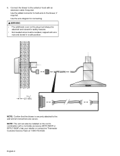
... a safe position. 13/16" (21 mm) NOTE: Confirm that the blower is securely attached to the blower, if required. NOTE: The unit can also be installed on the plug must always be attached and closed for safety reasons. • Not needed wires must be isolated, capped with wire nuts and stored... cable if required. Use the added connector to hard-wire to the wall and all connections are secure. English 4 Ask your retailer or contact the Thermador Customer Service Team at 1-800-735-4328. 6.
... a safe position. 13/16" (21 mm) NOTE: Confirm that the blower is securely attached to the blower, if required. NOTE: The unit can also be installed on the plug must always be attached and closed for safety reasons. • Not needed wires must be isolated, capped with wire nuts and stored... cable if required. Use the added connector to hard-wire to the wall and all connections are secure. English 4 Ask your retailer or contact the Thermador Customer Service Team at 1-800-735-4328. 6.