Installation Manual
Page 2
...Installation 2 Step 1: EXHAUST-AIR MODE 2 Step 2: PREPARING THE WALL 2 Step 3: INSTALLATION 3 Wire Diagram 5 Customer Support, Accessories & Parts back page Safety Definitions 9 WARNING This indicates that death or serious injuries may occur as a result of non-observance of this warning. 9 CAUTION This indicates that damage to important information and/or tips. This Thermador... Home Appliances Corporation 1901 Main Street, Suite 600 Irvine, CA 92614 Questions? 1-800-735-4328 www.thermador.com We look forward to hearing from you to the appliance or property may occur as a result of...
...Installation 2 Step 1: EXHAUST-AIR MODE 2 Step 2: PREPARING THE WALL 2 Step 3: INSTALLATION 3 Wire Diagram 5 Customer Support, Accessories & Parts back page Safety Definitions 9 WARNING This indicates that death or serious injuries may occur as a result of non-observance of this warning. 9 CAUTION This indicates that damage to important information and/or tips. This Thermador... Home Appliances Corporation 1901 Main Street, Suite 600 Irvine, CA 92614 Questions? 1-800-735-4328 www.thermador.com We look forward to hearing from you to the appliance or property may occur as a result of...
Installation Manual
Page 3
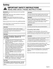
... tape and packaging before installing, switch power off at the service panel and lock the panel to the relevant safety regulations. INSTALLER: Please leave these instructions for proper combustion and exhausting of gases through the flue (chimney) of fire or electric shock, do not damage electrical wiring and other reproductive harm. WARNING To avoid electrical shock hazard, before using the appliance. Remove all applicable codes and regulations, including...
... tape and packaging before installing, switch power off at the service panel and lock the panel to the relevant safety regulations. INSTALLER: Please leave these instructions for proper combustion and exhausting of gases through the flue (chimney) of fire or electric shock, do not damage electrical wiring and other reproductive harm. WARNING To avoid electrical shock hazard, before using the appliance. Remove all applicable codes and regulations, including...
Installation Manual
Page 4
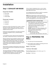
... and ovens. 9 IMPORTANT SAFETY INSTRUCTIONS • When attaching the outer wall blower, ensure that it is accessible for maintenance and repairs. • The plug-and-socket connections of the electric cables must be discharged in use of the ducting connected to the extractor hood except when used with official and statutory regulations only (e.g. Weight: 17.7 kg / 39 lbs Technical Information Electrical Requirements: 120 V; 60 Hz, max. 5.7 A Duct Size...
... and ovens. 9 IMPORTANT SAFETY INSTRUCTIONS • When attaching the outer wall blower, ensure that it is accessible for maintenance and repairs. • The plug-and-socket connections of the electric cables must be discharged in use of the ducting connected to the extractor hood except when used with official and statutory regulations only (e.g. Weight: 17.7 kg / 39 lbs Technical Information Electrical Requirements: 120 V; 60 Hz, max. 5.7 A Duct Size...
Installation Manual
Page 5
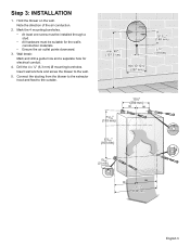
Hold the blower on the wall. Note the direction of the air conduction. 2. Mark the 4 mounting boreholes. • At least one screw must be installed through a stud. • All hardware must be suitable for electrical conduit. 4. ...Wall break: Mark and drill a guide hole and a separate hole for the wall's construction materials. • Ensure the air outlet points downward. 3. Connect the ducting from the blower to the extractor hood and feed to the wall. 5. Step 3: INSTALLATION 1. Drill the 4 x ¼'' (6,3 mm) Ø mounting boreholes. Insert wall anchors and screw the blower...
Hold the blower on the wall. Note the direction of the air conduction. 2. Mark the 4 mounting boreholes. • At least one screw must be installed through a stud. • All hardware must be suitable for electrical conduit. 4. ...Wall break: Mark and drill a guide hole and a separate hole for the wall's construction materials. • Ensure the air outlet points downward. 3. Connect the ducting from the blower to the extractor hood and feed to the wall. 5. Step 3: INSTALLATION 1. Drill the 4 x ¼'' (6,3 mm) Ø mounting boreholes. Insert wall anchors and screw the blower...
Installation Manual
Page 6
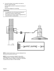
.../16" (21 mm) NOTE: Confirm that the blower is securely attached to the wall and all connections are secure. Ask your retailer or contact the Thermador Customer Service Team at 1-800-735-4328. Connect the blower to the blower, if required. English 4 Use the wire diagram for safety reasons. • Not needed wires must be isolated, capped with wire nuts and stored in combination with an extension cable if required.
.../16" (21 mm) NOTE: Confirm that the blower is securely attached to the wall and all connections are secure. Ask your retailer or contact the Thermador Customer Service Team at 1-800-735-4328. Connect the blower to the blower, if required. English 4 Use the wire diagram for safety reasons. • Not needed wires must be isolated, capped with wire nuts and stored in combination with an extension cable if required.

Installation Manual
Page 7
Wire Diagram speed 1 speed 2 speed 3 speed 4 N PE (red) (blue) (orange) (brown) (white) (green/yellow) NOTE: If using a three speed hood, connect speed 1 (red) , speed 2 (blue) and speed 4 (brown). Cap off speed 3 (orange). English 5
Wire Diagram speed 1 speed 2 speed 3 speed 4 N PE (red) (blue) (orange) (brown) (white) (green/yellow) NOTE: If using a three speed hood, connect speed 1 (red) , speed 2 (blue) and speed 4 (brown). Cap off speed 3 (orange). English 5


