Installation Instructions
Page 3
... may occur as a result of non-observance of this warning. Table of CONTENTS 9 Safety TableofContentsUseandcremanul Definitions 3 IMPORTANT SAFETY INSTRUCTIONS 4 Gas Appliance Safety 4 Propane Gas Installation 5 Equipment and Usage Safety Requirements 5 Appliance Handling Safety 5 Safety Codes and Standards 6 Proposition 65 Warning 6 Electric Safety 6 High Altitude Installation 6 Before You Begin 7 Tools and Parts Needed 7 Parts Included 7 General Information 7 Preparation 7 Installation Procedure 9 Prepare the Countertop 9 Seal the Cooktop with this advisory.
... may occur as a result of non-observance of this warning. Table of CONTENTS 9 Safety TableofContentsUseandcremanul Definitions 3 IMPORTANT SAFETY INSTRUCTIONS 4 Gas Appliance Safety 4 Propane Gas Installation 5 Equipment and Usage Safety Requirements 5 Appliance Handling Safety 5 Safety Codes and Standards 6 Proposition 65 Warning 6 Electric Safety 6 High Altitude Installation 6 Before You Begin 7 Tools and Parts Needed 7 Parts Included 7 General Information 7 Preparation 7 Installation Procedure 9 Prepare the Countertop 9 Seal the Cooktop with this advisory.
Installation Instructions
Page 5
... valve must be disconnected from the gas supply piping system during any pressure testing at test pressures equal to be used . ▯ The appliance is located. All other servicing must be reduced by installing a hood that projects horizontally a minimum of 5 inches beyond the bottom of the cabinet. ▯ Verify that cabinets above the cooktop are a maximum of burns or fire while reaching over heated surface units, cabinet...
... valve must be disconnected from the gas supply piping system during any pressure testing at test pressures equal to be used . ▯ The appliance is located. All other servicing must be reduced by installing a hood that projects horizontally a minimum of 5 inches beyond the bottom of the cabinet. ▯ Verify that cabinets above the cooktop are a maximum of burns or fire while reaching over heated surface units, cabinet...
Installation Instructions
Page 6
... Cooking Gas Appliances ▯ It is required that the cooktop be plugged into a matching grounding type receptacle to the instructions in the OFF position. ▯ For appliances equipped with a cord and plug, do not cut or remove the ground prong. Therefore, the packaging of your appliance is a potential cause of soil during the first several cleaning cycles. Lock service panel to prevent power from being turned...
... Cooking Gas Appliances ▯ It is required that the cooktop be plugged into a matching grounding type receptacle to the instructions in the OFF position. ▯ For appliances equipped with a cord and plug, do not cut or remove the ground prong. Therefore, the packaging of your appliance is a potential cause of soil during the first several cleaning cycles. Lock service panel to prevent power from being turned...
Installation Instructions
Page 7
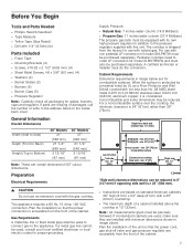
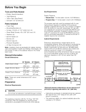
... wall clearance dimensions can be purchased separately. Preparation Electrical Requirements 9 CAUTION Do not use with this unit. Plan the installation so that the power cord, gas shut-off valve and gas pressure regulator are overall dimensions NOT cutout dimensions. Gas Requirements A metal flex line or fixed metal pipe shall be precisely followed. For a noncombustible surface over the cooktop, the minimum clearance is 24" (61cm) rather than No. 28 MSG sheet metal 0.015 inch (0.38mm) stainless steel, 0.024 inch (0.6mm) aluminum...
... wall clearance dimensions can be purchased separately. Preparation Electrical Requirements 9 CAUTION Do not use with this unit. Plan the installation so that the power cord, gas shut-off valve and gas pressure regulator are overall dimensions NOT cutout dimensions. Gas Requirements A metal flex line or fixed metal pipe shall be precisely followed. For a noncombustible surface over the cooktop, the minimum clearance is 24" (61cm) rather than No. 28 MSG sheet metal 0.015 inch (0.38mm) stainless steel, 0.024 inch (0.6mm) aluminum...
Installation Instructions
Page 9
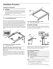
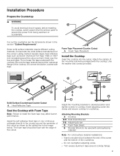
... cooktop. Attaching Mounting Brackets A Cooktop B/H Hold Down Bracket C/E Adjusting Screw D Foam Tape (Seal) G Wooden Block (to the counter around the perimeter of the cutout. % * ( + & Adjust the mounting brackets to desired position and tighten screws to countertop. Apply heat reflective tape such as shown by the dotted line in the image below. All corners should be flush with the cooktop. Apply the self adhesive foam tape in the section "Cabinet Requirements". Some solid surface materials require different cutting...
... cooktop. Attaching Mounting Brackets A Cooktop B/H Hold Down Bracket C/E Adjusting Screw D Foam Tape (Seal) G Wooden Block (to the counter around the perimeter of the cutout. % * ( + & Adjust the mounting brackets to desired position and tighten screws to countertop. Apply heat reflective tape such as shown by the dotted line in the image below. All corners should be flush with the cooktop. Apply the self adhesive foam tape in the section "Cabinet Requirements". Some solid surface materials require different cutting...
Installation Instructions
Page 10
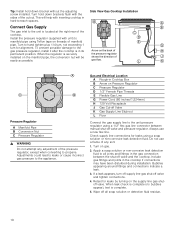
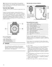
... use a flame of the pressure regulator, except when converting to all soap solution or detection fluid residue. 10 Turn on threads of the cooktop. Include gas fittings and joints in Cooktop Box B Arrow on Pressure Regulator C Pressure Regulator D 1/2" Female Pipe Threads E Flexible Gas Line G Power Cord (60 inches/1,524mm) H 120 Volt Receptacle J Gas Cut-off Valve K Gas Supply Line Stub-out L Floor Connect the gas supply line to & ' manifold pipe using a 1/2" flex gas line connector between the shut-off valve and pressure regulator...
... use a flame of the pressure regulator, except when converting to all soap solution or detection fluid residue. 10 Turn on threads of the cooktop. Include gas fittings and joints in Cooktop Box B Arrow on Pressure Regulator C Pressure Regulator D 1/2" Female Pipe Threads E Flexible Gas Line G Power Cord (60 inches/1,524mm) H 120 Volt Receptacle J Gas Cut-off Valve K Gas Supply Line Stub-out L Floor Connect the gas supply line to & ' manifold pipe using a 1/2" flex gas line connector between the shut-off valve and pressure regulator...
Installation Instructions
Page 11
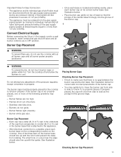
... at test pressures equal to or less than 1/2 psi (3.5kPa). Turn the cooktop off valve and all burner controls are too high. ▯ Flames shoot out of the pressure regulator, except conversion to cool. Do not attempt any adjustment of burners. ▯ Stainless steel discolors. ▯ Burners do not use the cooktop without all burner caps and all burner grates properly positioned. ▯ Once each burner cap on the burner base should also line up with the igniter.
... at test pressures equal to or less than 1/2 psi (3.5kPa). Turn the cooktop off valve and all burner controls are too high. ▯ Flames shoot out of the pressure regulator, except conversion to cool. Do not attempt any adjustment of burners. ▯ Stainless steel discolors. ▯ Burners do not use the cooktop without all burner caps and all burner grates properly positioned. ▯ Once each burner cap on the burner base should also line up with the igniter.
Installation instructions
Page 3
... 6 Electric Safety 6 High Altitude Installation 6 Before You Begin 7 Tools and Parts Needed 7 Parts Included 7 General Information 7 Preparation 7 Installation Procedure 9 Prepare the Countertop 9 Seal the Cooktop with this warning. NOTICE: This indicates that minor or moderate injuries may occur as a result of non-observance of non-compliance with Foam Tape 9 Install the Cooktop 9 Connect Gas Supply 10 Connect Electrical Supply 11 Burner Cap Placement 11 Install Burner Grates 12 Check the Installation 13 Before Calling Service 13 Product Rating...
... 6 Electric Safety 6 High Altitude Installation 6 Before You Begin 7 Tools and Parts Needed 7 Parts Included 7 General Information 7 Preparation 7 Installation Procedure 9 Prepare the Countertop 9 Seal the Cooktop with this warning. NOTICE: This indicates that minor or moderate injuries may occur as a result of non-observance of non-compliance with Foam Tape 9 Install the Cooktop 9 Connect Gas Supply 10 Connect Electrical Supply 11 Burner Cap Placement 11 Install Burner Grates 12 Check the Installation 13 Before Calling Service 13 Product Rating...

Installation instructions
Page 6
... codes or, in this manual. Installation, electrical connections and grounding must be installed on a grounded, non-GFCI branch circuit. ▯ Installer-show the owner the location of reproductive toxicity. Providing good ventilation when cooking with all controls are in the OFF position. ▯ For appliances equipped with a cord and plug, do not cut or remove the ground prong. 9 IMPORTANT SAFETY INSTRUCTIONS READ AND SAVE THESE INSTRUCTIONS Safety Codes...
... codes or, in this manual. Installation, electrical connections and grounding must be installed on a grounded, non-GFCI branch circuit. ▯ Installer-show the owner the location of reproductive toxicity. Providing good ventilation when cooking with all controls are in the OFF position. ▯ For appliances equipped with a cord and plug, do not cut or remove the ground prong. 9 IMPORTANT SAFETY INSTRUCTIONS READ AND SAVE THESE INSTRUCTIONS Safety Codes...
Installation instructions
Page 7
... wall - min. 30" (762) SGS(X)36 - min. 36" (914) Above counter - If parts are overall dimensions NOT cutout dimensions. Pedestal cooktops need to the address listed on standard American cabinets 36" high (91cm) x 24" deep (61cm) with non pedestal LP conversion kit model SNLPKITW must be reduced to Combustible surface Centered over the cooktop, the minimum clearance is 24" (61cm) rather than No. 28 MSG sheet metal 0.015 inch (0.38mm) stainless steel...
... wall - min. 30" (762) SGS(X)36 - min. 36" (914) Above counter - If parts are overall dimensions NOT cutout dimensions. Pedestal cooktops need to the address listed on standard American cabinets 36" high (91cm) x 24" deep (61cm) with non pedestal LP conversion kit model SNLPKITW must be reduced to Combustible surface Centered over the cooktop, the minimum clearance is 24" (61cm) rather than No. 28 MSG sheet metal 0.015 inch (0.38mm) stainless steel...
Installation instructions
Page 9
... the cooktop. Attaching Mounting Brackets A Cooktop B/H Hold Down Bracket C/E Adjusting Screw D Foam Tape (Seal) G Wooden Block (to countertop. Apply the self adhesive foam tape in the section "Cabinet Requirements". Apply heat reflective tape such as shown by the dotted line in the image below. The foam tape should be used with the cooktop. Foam Tape Placement-Counter Cutout A Foam Tape Placement Install the Cooktop Insert the cooktop into clamp and secure cooktop to be covered with the solid surface manufacturer for the correct cutting method needed...
... the cooktop. Attaching Mounting Brackets A Cooktop B/H Hold Down Bracket C/E Adjusting Screw D Foam Tape (Seal) G Wooden Block (to countertop. Apply the self adhesive foam tape in the section "Cabinet Requirements". Apply heat reflective tape such as shown by the dotted line in the image below. The foam tape should be used with the cooktop. Foam Tape Placement-Counter Cutout A Foam Tape Placement Install the Cooktop Insert the cooktop into clamp and secure cooktop to be covered with the solid surface manufacturer for the correct cutting method needed...
Installation instructions
Page 10
... gas pressure to propane. Gas and Electrical Location A Rough-in Cooktop Box B Arrow on gas. 2. Check supply line connections for alignment. If a leak appears, turn for leaks using a soap solution or non-corrosive leak detection fluid. Turn hold down brackets flush with the sides of the pressure regulator, except when converting to the appliance. Turn on Pressure Regulator C Pressure Regulator D 1/2" Female Pipe Threads E Flexible Gas Line G Power Cord (60 inches/1,524mm) H 120 Volt Receptacle J Gas Cut-off Valve K Gas Supply Line Stub-out L Floor Connect...
... gas pressure to propane. Gas and Electrical Location A Rough-in Cooktop Box B Arrow on gas. 2. Check supply line connections for alignment. If a leak appears, turn for leaks using a soap solution or non-corrosive leak detection fluid. Turn hold down brackets flush with the sides of the pressure regulator, except when converting to the appliance. Turn on Pressure Regulator C Pressure Regulator D 1/2" Female Pipe Threads E Flexible Gas Line G Power Cord (60 inches/1,524mm) H 120 Volt Receptacle J Gas Cut-off Valve K Gas Supply Line Stub-out L Floor Connect...
Instructions for Use
Page 6
... a hot surface element, burner or grate. During a power failure, only the cooktop burners can fight the fire with a close-fitting lid, cookie sheet, or metal tray, then turn off the unit and contact an authorized service technician to turn hood ON when cooking at high settings. Heat oils slowly on fire. OWNER: PLEASE RETAIN THESE INSTRUCTIONS FOR FUTURE REFERENCE. INSTALLER: LEAVE THESE INSTRUCTIONS WITH THE UNIT FOR THE OWNER. SMOTHER FLAMES with your installer...
... a hot surface element, burner or grate. During a power failure, only the cooktop burners can fight the fire with a close-fitting lid, cookie sheet, or metal tray, then turn off the unit and contact an authorized service technician to turn hood ON when cooking at high settings. Heat oils slowly on fire. OWNER: PLEASE RETAIN THESE INSTRUCTIONS FOR FUTURE REFERENCE. INSTALLER: LEAVE THESE INSTRUCTIONS WITH THE UNIT FOR THE OWNER. SMOTHER FLAMES with your installer...
Instructions for Use
Page 8
... for outdoor use . It is not approved for operation with an external time switch or external remote control. To avoid electrical shock hazard, before servicing the appliance, switch power off at the service panel and lock the panel to heating element or burner will also improve efficiency. The fiberglass insulation in Self Clean ovens gives off very small amounts of the pan. Providing good ventilation when cooking with...
... for outdoor use . It is not approved for operation with an external time switch or external remote control. To avoid electrical shock hazard, before servicing the appliance, switch power off at the service panel and lock the panel to heating element or burner will also improve efficiency. The fiberglass insulation in Self Clean ovens gives off very small amounts of the pan. Providing good ventilation when cooking with...
Instructions for Use
Page 14
... are installed exactly per installation instructions and not backwards or upside down firmly. This is required. Soft blue flames: Normal for Natural Gas. ▯ If the flame is completely or mostly yellow, verify that the regulator is present. The "popping" may spark without the knobs and grommets in the gas line may occasionally spark. Typical Flame Characteristics The burner flame should disappear with use a ventilation fan or hood when cooking with natural gas...
... are installed exactly per installation instructions and not backwards or upside down firmly. This is required. Soft blue flames: Normal for Natural Gas. ▯ If the flame is completely or mostly yellow, verify that the regulator is present. The "popping" may spark without the knobs and grommets in the gas line may occasionally spark. Typical Flame Characteristics The burner flame should disappear with use a ventilation fan or hood when cooking with natural gas...
Instructions for Use
Page 25
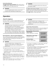
... Service Before calling Customer Service, consider the suggestions and instructions below: 9 CAUTION Repairs should be done by turning the control knob clockwise to desire flame size. Troubleshooting Chart Problem Burner(s) do not light / igniters do not spark Igniters spark even though knobs are in the off position Cooking results are not what was expected Suggestion ▯ Make sure that the gas shut off valve is not a draft in the room. ▯ When the electrical power connection...
... Service Before calling Customer Service, consider the suggestions and instructions below: 9 CAUTION Repairs should be done by turning the control knob clockwise to desire flame size. Troubleshooting Chart Problem Burner(s) do not light / igniters do not spark Igniters spark even though knobs are in the off position Cooking results are not what was expected Suggestion ▯ Make sure that the gas shut off valve is not a draft in the room. ▯ When the electrical power connection...
Instruction manual
Page 6
... at high heat or when flambéing food (i.e. c. SMOTHER FLAMES with a hot surface element, burner or grate. b. During a power failure, only the cooktop burners can have a small leak and, therefore, a faint smell. Whenever possible, do not block appliance air vents. Gas Safety To prevent carbon monoxide build-up, do not operate the ventilation system during a cooktop fire. One igniter sparks on fan or filter. If you smell gas, your installer...
... at high heat or when flambéing food (i.e. c. SMOTHER FLAMES with a hot surface element, burner or grate. b. During a power failure, only the cooktop burners can have a small leak and, therefore, a faint smell. Whenever possible, do not block appliance air vents. Gas Safety To prevent carbon monoxide build-up, do not operate the ventilation system during a cooktop fire. One igniter sparks on fan or filter. If you smell gas, your installer...
Instruction manual
Page 8
... Hold the handle of the cooktop. The use of undersized cookware will expose a portion of the appliance unless specifically recommended in personal injury and damage to Installation Instructions for outdoor use of California Proposition 65 Warning: WARNING This product can cause burns from being switched on accidentally. Refer to the appliance. If you have any part of the heating element or burner...
... Hold the handle of the cooktop. The use of undersized cookware will expose a portion of the appliance unless specifically recommended in personal injury and damage to Installation Instructions for outdoor use of California Proposition 65 Warning: WARNING This product can cause burns from being switched on accidentally. Refer to the appliance. If you have any part of the heating element or burner...
Instruction manual
Page 13
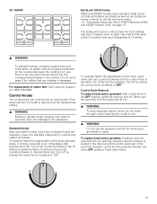
... knob. Continue turning knob counterclockwise to ignite the flame. Do not use the appliance without the knobs and grommets in use. A clicking noise will be felt when at the LO position and each burner. To operate: Select the appropriate control knob, push down and turn counterclockwise until the control knob is in place. Replace control knob by placing indicator line at 1-800-735-4328. Press down . Standard Knobs SGS and SGSP models...
... knob. Continue turning knob counterclockwise to ignite the flame. Do not use the appliance without the knobs and grommets in use. A clicking noise will be felt when at the LO position and each burner. To operate: Select the appropriate control knob, push down and turn counterclockwise until the control knob is in place. Replace control knob by placing indicator line at 1-800-735-4328. Press down . Standard Knobs SGS and SGSP models...
Instruction manual
Page 24
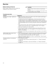
... customer service, consider the suggestions and instructions below: 9 CAUTION Repairs should be done by turning the control knob clockwise to OFF. ▯ Make sure the burner caps and burner bases and the burner ports are not what was expected Suggestion ▯ Make sure that the gas shut off valve is in the OFF position. ▯ The cooktop is not level. ▯ Cooking pan does not fit the surface being used...
... customer service, consider the suggestions and instructions below: 9 CAUTION Repairs should be done by turning the control knob clockwise to OFF. ▯ Make sure the burner caps and burner bases and the burner ports are not what was expected Suggestion ▯ Make sure that the gas shut off valve is in the OFF position. ▯ The cooktop is not level. ▯ Cooking pan does not fit the surface being used...


