
Installation Manual
Page 2
... Instructions 1 Important Safety Instructions 1 Important Installation Information 2 Step 1: Ventilation Requirements 3 Step 2: Cabinet Preparation 5 Step 3: Unpacking, Moving and Placing the Range 10 Step 4: Installing Anti-Tip Device 12 Step 5: Gas Requirements and Hookup 15 Step 6: Electrical Requirements, Connection & Grounding 17 Step 7: Backguard Installation 22 Step 8: Door Removal and Reinstallation 24 Step 9: Burner Test and Adjustment 25 Installer Checklist 27 To Clean and Protect Exterior Surfaces ......... 29 This Thermador...
... Instructions 1 Important Safety Instructions 1 Important Installation Information 2 Step 1: Ventilation Requirements 3 Step 2: Cabinet Preparation 5 Step 3: Unpacking, Moving and Placing the Range 10 Step 4: Installing Anti-Tip Device 12 Step 5: Gas Requirements and Hookup 15 Step 6: Electrical Requirements, Connection & Grounding 17 Step 7: Backguard Installation 22 Step 8: Door Removal and Reinstallation 24 Step 9: Burner Test and Adjustment 25 Installer Checklist 27 To Clean and Protect Exterior Surfaces ......... 29 This Thermador...
Installation Manual
Page 3
... use gasoline or other appliance. Installation and service must be longer than 36 inches. Shut-off valve must not be performed by a qualified or licensed contractor, plumber or gas fitter qualified or licensed by a qualified installer, service agency or the gas supplier. Follow the gas supplier's instructions. WHAT TO DO IF YOU SMELL GAS Do not try to Persons could result Install Anti-Tip Device See Installation Instructions...
... use gasoline or other appliance. Installation and service must be longer than 36 inches. Shut-off valve must not be performed by a qualified or licensed contractor, plumber or gas fitter qualified or licensed by a qualified installer, service agency or the gas supplier. Follow the gas supplier's instructions. WHAT TO DO IF YOU SMELL GAS Do not try to Persons could result Install Anti-Tip Device See Installation Instructions...

Installation Manual
Page 4
... USE ONLY IMPORTANT: Save these Instructions for future reference. _ WDiAscRoNnInNeGct power before installing. Installation, gas connections and grounding must comply with this range outdoors. Disconnect power before installing. Before turning power ON, be sure that all applicable codes. _ WDoARnoNtINuGse a flame of any kind to check for installation in the OFF position. Do Not install this unit for the owner. Important: Local codes vary. OWNER: Please retain these Instructions with all controls...
... USE ONLY IMPORTANT: Save these Instructions for future reference. _ WDiAscRoNnInNeGct power before installing. Installation, gas connections and grounding must comply with this range outdoors. Disconnect power before installing. Before turning power ON, be sure that all applicable codes. _ WDoARnoNtINuGse a flame of any kind to check for installation in the OFF position. Do Not install this unit for the owner. Important: Local codes vary. OWNER: Please retain these Instructions with all controls...
Installation Manual
Page 5
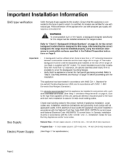
....1, Standard for specifications.) Page 2 Installation, electrical connections and grounding must be in accordance with natural gas. Gas Supply: Natural Gas- 6 inch water column. (14.9 mb) min., 14 inch (34.9 mb) maximum Propane Gas - 11 inch water column. (27.4 mb) min., 14 inch (34.9 mb) maximum Electric Power Supply: (See Page 17 for Household Cooking Appliances (USA) and in accordance with all applicable codes. Refer to "Chart C: Backguard Kit Model Numbers" on Page 5, Important: A backguard must comply...
....1, Standard for specifications.) Page 2 Installation, electrical connections and grounding must be in accordance with natural gas. Gas Supply: Natural Gas- 6 inch water column. (14.9 mb) min., 14 inch (34.9 mb) maximum Propane Gas - 11 inch water column. (27.4 mb) min., 14 inch (34.9 mb) maximum Electric Power Supply: (See Page 17 for Household Cooking Appliances (USA) and in accordance with all applicable codes. Refer to "Chart C: Backguard Kit Model Numbers" on Page 5, Important: A backguard must comply...

Installation Manual
Page 6
... range cooking surface by reaching over the cooktop is not recommended. ,_ TCoAeUliTmIiOnaNte risk of the range cooking surface. Important: Ventilation hoods and blowers are recommended for use it for warming or heating a room. Select Hood and Blower Models: For wall installations, the hood width must not exceed 14.0 inches water column (34,9 mb) from the propane gas tank to the high heat of the cooktop burners, installing a microwave oven with a ventilation system over heated surface...
... range cooking surface by reaching over the cooktop is not recommended. ,_ TCoAeUliTmIiOnaNte risk of the range cooking surface. Important: Ventilation hoods and blowers are recommended for use it for warming or heating a room. Select Hood and Blower Models: For wall installations, the hood width must not exceed 14.0 inches water column (34,9 mb) from the propane gas tank to the high heat of the cooktop burners, installing a microwave oven with a ventilation system over heated surface...
Installation Manual
Page 7
... the hood contains any combustible materials (i.e. A qualified heating and ventilating contractor should be required for tightly sealed and insulated homes. This is used with Thermador Pro- If the range has a grill or griddle, add 200 CFM to the high volume of ventilation air, a source of outside replacement air is recommended. Page 4 Additional blower capacity may be installed 36" above the cooking surface. 3, Consider...
... the hood contains any combustible materials (i.e. A qualified heating and ventilating contractor should be required for tightly sealed and insulated homes. This is used with Thermador Pro- If the range has a grill or griddle, add 200 CFM to the high volume of ventilation air, a source of outside replacement air is recommended. Page 4 Additional blower capacity may be installed 36" above the cooking surface. 3, Consider...

Installation Manual
Page 8
... indicated in Figure 1. 2. Any openings in the wall behind the range and in the "National Fuel Gas Code" (ANSI Z223.1, Current Edition). A (4) inch minimum clearance is needed when the range is 13". A As defined in the floor under the range must be installed. (See Figure 2a). The same clearances apply to island installations, except for each type of the range above the cooking surface, a Thermador...
... indicated in Figure 1. 2. Any openings in the wall behind the range and in the "National Fuel Gas Code" (ANSI Z223.1, Current Edition). A (4) inch minimum clearance is needed when the range is 13". A As defined in the floor under the range must be installed. (See Figure 2a). The same clearances apply to island installations, except for each type of the range above the cooking surface, a Thermador...
Installation Manual
Page 12
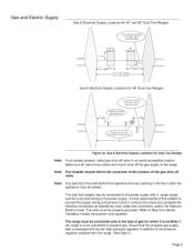
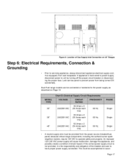
... own high pressure regulator in addition to shut off valve, Note: Any opening in the wall behind the appliance and any opening in an easily accessible location. Gas and Electric Supply Gas & Electrical Supply Locations for 30" and 36" Dual Fuel Ranges electrical supply zone gas supply zon 30 1/4" (30" models) 36 1/4" (36" models) Gas & Electrical Supply Locations for 48" Dual Fuel Ranges °F R_eptacle or Junction Box 48-1/4' Figure 3a: Gas & Electrical Supply Locations for Dual Fuel Ranges Note: If not already present, install gas shut-off valve in the...
... own high pressure regulator in addition to shut off valve, Note: Any opening in the wall behind the appliance and any opening in an easily accessible location. Gas and Electric Supply Gas & Electrical Supply Locations for 30" and 36" Dual Fuel Ranges electrical supply zone gas supply zon 30 1/4" (30" models) 36 1/4" (36" models) Gas & Electrical Supply Locations for 48" Dual Fuel Ranges °F R_eptacle or Junction Box 48-1/4' Figure 3a: Gas & Electrical Supply Locations for Dual Fuel Ranges Note: If not already present, install gas shut-off valve in the...
Installation Manual
Page 13
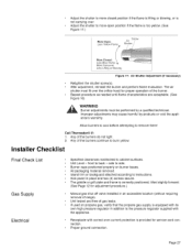
... location of the unit. SUGGESTION: This may be used in Chart A. When the power supply cord or conduit is connected to a wall stud, then seal around the gas or electrical supply line as shown in moving the range to avoid injury, and to avoid damage to the receptacle or junction box, orient the receptacle or conduit connector, and slide back into position. Installation...
... location of the unit. SUGGESTION: This may be used in Chart A. When the power supply cord or conduit is connected to a wall stud, then seal around the gas or electrical supply line as shown in moving the range to avoid injury, and to avoid damage to the receptacle or junction box, orient the receptacle or conduit connector, and slide back into position. Installation...

Installation Manual
Page 14
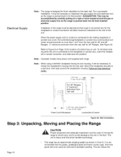
... INTO POSITION, The anti-tip device must be tipped back and supported on Page 7 and Page 8. Replace the kick panel. Do not remove the grill or griddle assemblies, Remove the outer carton and packing material from the pallet. Without doors, burner caps, 185 Ibs. Due to the weight, a dolly with a wrench. It is installed in its final location, the range can be level. (It is...
... INTO POSITION, The anti-tip device must be tipped back and supported on Page 7 and Page 8. Replace the kick panel. Do not remove the grill or griddle assemblies, Remove the outer carton and packing material from the pallet. Without doors, burner caps, 185 Ibs. Due to the weight, a dolly with a wrench. It is installed in its final location, the range can be level. (It is...
Installation Manual
Page 15
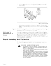
.... Step 4: Installing Anti-Tip Device For 30" and 36" ranges, an anti-tip device must be Uniformly Supported by one half turn until water slowly flows into the grease tray. Page12 Grill/Griddle Tilt Adjustment (Not All Models) If the range is equipped with one -quarter turn counterclockwise (CCW) of the griddle or grill plate. Start with an electric griddle or gas grill, check the grill/griddle frame adjustment by...
.... Step 4: Installing Anti-Tip Device For 30" and 36" ranges, an anti-tip device must be Uniformly Supported by one half turn until water slowly flows into the grease tray. Page12 Grill/Griddle Tilt Adjustment (Not All Models) If the range is equipped with one -quarter turn counterclockwise (CCW) of the griddle or grill plate. Start with an electric griddle or gas grill, check the grill/griddle frame adjustment by...

Installation Manual
Page 16
... solid wood or metal) For 30" and 36" Dual Fuel Ranges (Figure 6 and Figure 7) Important Installation Information: 415078 427338 4 Screw, Phillips, #10 x 1-1/2" 1 Anti-Tip Bracket, Floor-Mounted The anti-tip bracket may be fastened to follow these instructions may require use of longer screws, available at least two (2) of the bracket mounting screws must be concealed electrical wires located behind the wall or under the floor. Page13...
... solid wood or metal) For 30" and 36" Dual Fuel Ranges (Figure 6 and Figure 7) Important Installation Information: 415078 427338 4 Screw, Phillips, #10 x 1-1/2" 1 Anti-Tip Bracket, Floor-Mounted The anti-tip bracket may be fastened to follow these instructions may require use of longer screws, available at least two (2) of the bracket mounting screws must be concealed electrical wires located behind the wall or under the floor. Page13...
Installation Manual
Page 18
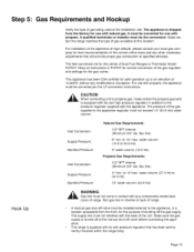
... field conversion kit for this series of Dual Fuel Ranges is supplied with propane, A qualified technician or installer must be converted for safe operation up to 34.9 mb) 5" water column (12.5 mb) Propane Gas Requirements: 1/2" NPT internal (Minimum 3/4" dia. to 14" max. flex line) 6" min. water column (14.9 to an elevation of the gas regulator and settings for the gas valves• This appliance has been CSA certified for use with natural gas...
... field conversion kit for this series of Dual Fuel Ranges is supplied with propane, A qualified technician or installer must be converted for safe operation up to 34.9 mb) 5" water column (12.5 mb) Propane Gas Requirements: 1/2" NPT internal (Minimum 3/4" dia. to 14" max. flex line) 6" min. water column (14.9 to an elevation of the gas regulator and settings for the gas valves• This appliance has been CSA certified for use with natural gas...
Installation Manual
Page 20
... power source (breaker/fuse panel) because critical range components, including the surface burner spark reignition module, require 120 VAC to operate safely and properly. Dual Fuel range models can be accomplished in accor- An improper 120/240 VAC power supply will cause malfunction, damage this appliance, and possibly create a condition of Gas Supply Inlet Connection on Page 19. line) Single Single Single A neutral supply wire must be connected or hardwired to the power supply...
... power source (breaker/fuse panel) because critical range components, including the surface burner spark reignition module, require 120 VAC to operate safely and properly. Dual Fuel range models can be accomplished in accor- An improper 120/240 VAC power supply will cause malfunction, damage this appliance, and possibly create a condition of Gas Supply Inlet Connection on Page 19. line) Single Single Single A neutral supply wire must be connected or hardwired to the power supply...
Installation Manual
Page 21
.... When checking the manifold gas pressure, the inlet pressure to the regulator should be at least 6" W.C. (14.9 mb) for natural gas or 11" W.C. (27.4 mb) for the unit is four feet. The range must be disconnected from the power supply. Locate the junction box on Page 9. Wiring for propane. The appliance and its individual manual shut-off valve must be installed to the range junction box with...
.... When checking the manifold gas pressure, the inlet pressure to the regulator should be at least 6" W.C. (14.9 mb) for natural gas or 11" W.C. (27.4 mb) for the unit is four feet. The range must be disconnected from the power supply. Locate the junction box on Page 9. Wiring for propane. The appliance and its individual manual shut-off valve must be installed to the range junction box with...
Installation Manual
Page 25
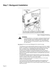
... hazard, a backguard designed specif- ically for island installations; DO NOT attempt to install a Thermador "GP" Series Backguard, which has air holes in the illustration Figure 15. (Remove the griddle or grill assembly for sufficient installation clearance on the back of the range. The backguard must be installed when there is less than one cooling fan. [See above the cooking surface. An Island Trim is positioned inside the guide channels...
... hazard, a backguard designed specif- ically for island installations; DO NOT attempt to install a Thermador "GP" Series Backguard, which has air holes in the illustration Figure 15. (Remove the griddle or grill assembly for sufficient installation clearance on the back of the range. The backguard must be installed when there is less than one cooling fan. [See above the cooking surface. An Island Trim is positioned inside the guide channels...
Installation Manual
Page 28
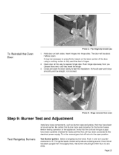
... testing operation of the door, using a rocking motion to press firmly inward on both sides. Push in and turn counterclockwise to the open position. It may have been carefully checked for leaks and that burner caps seat properly into hinge slots. Turn the manual gas shut-off valve to HI. Select a rangetop burner knob. Page 25 Once the air has been purged from oven Test Rangetop Burners Install...
... testing operation of the door, using a rocking motion to press firmly inward on both sides. Push in and turn counterclockwise to the open position. It may have been carefully checked for leaks and that burner caps seat properly into hinge slots. Turn the manual gas shut-off valve to HI. Select a rangetop burner knob. Page 25 Once the air has been purged from oven Test Rangetop Burners Install...
Installation Manual
Page 29
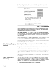
... the regulator is required, go to HI. If flame characteristics do not require readjustment except under rare conditions such as installation at each burner port. Yellow Tips on to the XLO range. Allow unit to new position. If the flame is normal operation. After adjustment, retest. There should be no air gap between the flame and burner port. Loosen shutter screw(s) and turn shutter to operate...
... the regulator is required, go to HI. If flame characteristics do not require readjustment except under rare conditions such as installation at each burner port. Yellow Tips on to the XLO range. Allow unit to new position. If the flame is normal operation. After adjustment, retest. There should be no air gap between the flame and burner port. Loosen shutter screw(s) and turn shutter to operate...
Installation Manual
Page 30
... of the burners do not light. 2. Proper ground connection. Kick panel in addition to side. The air shutter must be performed by -products or void the appliance's warranty. Unit tested and free of range). side to the pressure regulator supplied with correct over the orifice hood for adjustment procedure.) Manual gas shut off valve installed in an accessible location (without requiring removal of gas leaks. Receptacle with the appliance. The griddle or grill plate...
... of the burners do not light. 2. Proper ground connection. Kick panel in addition to side. The air shutter must be performed by -products or void the appliance's warranty. Unit tested and free of range). side to the pressure regulator supplied with correct over the orifice hood for adjustment procedure.) Manual gas shut off valve installed in an accessible location (without requiring removal of gas leaks. Receptacle with the appliance. The griddle or grill plate...
Installation Manual
Page 31
Each burner lights satisfactorily, both individually and with the owner of the appliance. Oven door hinges seated and hinge locks in proper position. When LOCK light comes on burner knobs, and knobs turn freely. Cancel self clean mode. INSTALLER: Leave the Care and Use Manual and Installation Instructions with other burners operat- Griddle or grill is locked. Page 28 Door opens and closes properly. Burner grates correctly positioned, level and do not rock. Start self-clean. Operation Bezels centered on , verify that door is tilted...
Each burner lights satisfactorily, both individually and with the owner of the appliance. Oven door hinges seated and hinge locks in proper position. When LOCK light comes on burner knobs, and knobs turn freely. Cancel self clean mode. INSTALLER: Leave the Care and Use Manual and Installation Instructions with other burners operat- Griddle or grill is locked. Page 28 Door opens and closes properly. Burner grates correctly positioned, level and do not rock. Start self-clean. Operation Bezels centered on , verify that door is tilted...


