
Parts List
Page 4
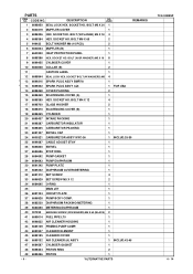
... FUEL PIPE L70 1 42 6696832 AIR CLEANER HOUSING 1 43 6685139 PRIMING PUMP COMP. 1 44 6690347 CLEANER ELEMENT 1 45 6699185 CLEANER COVER 1 46 6699132 AIR CLEANER (A) ASS'Y 1 INCLUD.42-45 47 6684587 CYLINDER GASKET 1 48 6698404 PISTON RING 2 49 6699456 PISTON 1 - 4 - *ALTERNATIVE PARTS TCG 24EBSP 4 - 14 SOCKET HD. PARTS ITEM NO. USED 1 6698950 SEAL LOCK HEX. SOCKET BOLT (W/WASHERS) M5 4 * 13 6699316 SPARK PLUG...
... FUEL PIPE L70 1 42 6696832 AIR CLEANER HOUSING 1 43 6685139 PRIMING PUMP COMP. 1 44 6690347 CLEANER ELEMENT 1 45 6699185 CLEANER COVER 1 46 6699132 AIR CLEANER (A) ASS'Y 1 INCLUD.42-45 47 6684587 CYLINDER GASKET 1 48 6698404 PISTON RING 2 49 6699456 PISTON 1 - 4 - *ALTERNATIVE PARTS TCG 24EBSP 4 - 14 SOCKET HD. PARTS ITEM NO. USED 1 6698950 SEAL LOCK HEX. SOCKET BOLT (W/WASHERS) M5 4 * 13 6699316 SPARK PLUG...
Parts List
Page 5
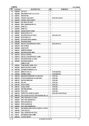
... 6699197 SWITCH WIRE SET 1 FOR (SL) * 94 6699196 NUT M5 2 FOR (SL) * 95 6699192 STOP LEVER 1 FOR (SL) * 96 6699191 LONG LEVER 1 FOR (SL) * 97 6699193 RETURN SPRING 1 FOR (SL) * 98 6699190 STAY SET 1 FOR (SL) * 99 6699133 THROTTLE LEVER (A) ASS'Y 1 INCLUD.91-98 FOR (SL) 100 6699176 HEX. PARTS ITEM NO. BOLT (W/SP.WASHER) M5 X 12 1 101 6695492 HEX. CODE NO. 50...
... 6699197 SWITCH WIRE SET 1 FOR (SL) * 94 6699196 NUT M5 2 FOR (SL) * 95 6699192 STOP LEVER 1 FOR (SL) * 96 6699191 LONG LEVER 1 FOR (SL) * 97 6699193 RETURN SPRING 1 FOR (SL) * 98 6699190 STAY SET 1 FOR (SL) * 99 6699133 THROTTLE LEVER (A) ASS'Y 1 INCLUD.91-98 FOR (SL) 100 6699176 HEX. PARTS ITEM NO. BOLT (W/SP.WASHER) M5 X 12 1 101 6695492 HEX. CODE NO. 50...

Parts List
Page 6
... CLUTCH WASHER (B) 2 116 6685337 FLYWHEEL NUT 1 117 323212 BOLT WASHER M8 (BLACK) 1 118 6698388 HEX. SOCKET HD. PARTS ITEM NO. BOLT M5 X 30 (10 PCS.) 1 163 6695414 SCREW 5 X 12/W.S 1 164 6600005 CAP 1 165 6600006 SPRING 1 166 6684737 BOLT (W/PLUS) M6 X 8 1 167 6600007 LOCK PIN 1 * 168 6699441 CUTTER HOLDER (A) 1 FOR EUROPE * 169 6698659 CUTTER HOLDER (B) 1 FOR EUROPE * 170 6699188 NUT COVER 1 FOR EUROPE - 6 - *ALTERNATIVE PARTS...
... CLUTCH WASHER (B) 2 116 6685337 FLYWHEEL NUT 1 117 323212 BOLT WASHER M8 (BLACK) 1 118 6698388 HEX. SOCKET HD. PARTS ITEM NO. BOLT M5 X 30 (10 PCS.) 1 163 6695414 SCREW 5 X 12/W.S 1 164 6600005 CAP 1 165 6600006 SPRING 1 166 6684737 BOLT (W/PLUS) M6 X 8 1 167 6600007 LOCK PIN 1 * 168 6699441 CUTTER HOLDER (A) 1 FOR EUROPE * 169 6698659 CUTTER HOLDER (B) 1 FOR EUROPE * 170 6699188 NUT COVER 1 FOR EUROPE - 6 - *ALTERNATIVE PARTS...

Parts List
Page 7
... LEVEL MARK 1 FOR EUROPE 190 6699445 MAIN PIPE 1 191 6698514 DRIVE SHAFT 1 * 192 6696493 HANGER 1 FOR EUROPE * 193 6698515 CAP (A) 1 FOR EUROPE * 194 6699450 WIRE CLAMP 2 FOR (S) * 195 6696981 GUARD 1 FOR USA * 196 323210 BOLT WASHER M4 (BLACK) 2 FOR USA * 197 6685068 MACHINE SCREW (W/SP. USED REMARKS 1 FOR EUROPE * 172 6698794 COVER 1 * 172 6698937 COVER 1 FOR USA 173 NYLON CORD 1 174 6698795 SET SCREW...
... LEVEL MARK 1 FOR EUROPE 190 6699445 MAIN PIPE 1 191 6698514 DRIVE SHAFT 1 * 192 6696493 HANGER 1 FOR EUROPE * 193 6698515 CAP (A) 1 FOR EUROPE * 194 6699450 WIRE CLAMP 2 FOR (S) * 195 6696981 GUARD 1 FOR USA * 196 323210 BOLT WASHER M4 (BLACK) 2 FOR USA * 197 6685068 MACHINE SCREW (W/SP. USED REMARKS 1 FOR EUROPE * 172 6698794 COVER 1 * 172 6698937 COVER 1 FOR USA 173 NYLON CORD 1 174 6698795 SET SCREW...
Owner's Manual
Page 2
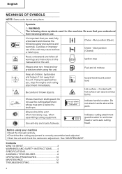
... a trimmer head or semi-auto cutting head. Shows maximum shaft speed. Indicate handle location. Do not attach handle above this manual and on the unit. Ignition stop Always wear eye, head and ear protectors when using your machine • Read the manual carefully. • Check that you , stop the engine and cutting attachment immediately. Indicates cutting attachment guard location for the machine. Contents WHAT IS WHAT 3 WARNINGS AND SAFETY INSTRUCTIONS ........ 4 SPECIFICATIONS 6 ASSEMBLY PROCEDURES 8 OPERATING PROCEDURES 10 MAINTENANCE 12 TROUBLESHOOTING...
... a trimmer head or semi-auto cutting head. Shows maximum shaft speed. Indicate handle location. Do not attach handle above this manual and on the unit. Ignition stop Always wear eye, head and ear protectors when using your machine • Read the manual carefully. • Check that you , stop the engine and cutting attachment immediately. Indicates cutting attachment guard location for the machine. Contents WHAT IS WHAT 3 WARNINGS AND SAFETY INSTRUCTIONS ........ 4 SPECIFICATIONS 6 ASSEMBLY PROCEDURES 8 OPERATING PROCEDURES 10 MAINTENANCE 12 TROUBLESHOOTING...
Owner's Manual
Page 3
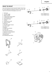
Cutting attachment guard 5. Fuel cap 2. Harness 5 11.Throttle trigger lockout 12.Choke lever 13. Drive shaft tube 7. Engine 14.Angle transmission 15.Joint case 16.Combi box spanner 17.Spanner (if so equipped) 18.Hex bar wrench 19.Swivel cap 20.Handling instructions 10 16 6 ... 9. Use the instructions that apply to your unit. Cutting attachment 6. Throttle trigger 3. English WHAT IS WHAT Since this manual covers several models, there may be some difference between pictures and your unit. 5 14 1. Handle 8. Starter handle 4. Ignition switch 10....
Cutting attachment guard 5. Fuel cap 2. Harness 5 11.Throttle trigger lockout 12.Choke lever 13. Drive shaft tube 7. Engine 14.Angle transmission 15.Joint case 16.Combi box spanner 17.Spanner (if so equipped) 18.Hex bar wrench 19.Swivel cap 20.Handling instructions 10 16 6 ... 9. Use the instructions that apply to your unit. Cutting attachment 6. Throttle trigger 3. English WHAT IS WHAT Since this manual covers several models, there may be some difference between pictures and your unit. 5 14 1. Handle 8. Starter handle 4. Ignition switch 10....

Owner's Manual
Page 4
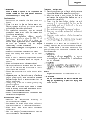
... in area where fuel vapors cannot reach sparks or open flames from water heaters, electric motors or switches, furnaces. WARNING Never modify the unit/machine in permanent hearing impairment. Wear approved hearing protection. Replace damaged parts. Do not use your surroundings. etc. 4 Remove safety equipment immediately upon shutting off engine. ○ Wear head protection. ○ Never start or run the engine inside a closed...
... in area where fuel vapors cannot reach sparks or open flames from water heaters, electric motors or switches, furnaces. WARNING Never modify the unit/machine in permanent hearing impairment. Wear approved hearing protection. Replace damaged parts. Do not use your surroundings. etc. 4 Remove safety equipment immediately upon shutting off engine. ○ Wear head protection. ○ Never start or run the engine inside a closed...
Owner's Manual
Page 5
...; Keep others away when making carburetor adjustments. ○ Use only genuine Tanaka replacement parts as recommended by the manufacturer. CAUTION Do not disassemble the recoil starter. CAUTION Indicates a possibility of your Tanaka dealer if you are approached. ○ Always keep the engine on the ground when running . ○ Keep cutting attachment below waist level. ○ When relocating to a new work area, be emptied after...
...; Keep others away when making carburetor adjustments. ○ Use only genuine Tanaka replacement parts as recommended by the manufacturer. CAUTION Do not disassemble the recoil starter. CAUTION Indicates a possibility of your Tanaka dealer if you are approached. ○ Always keep the engine on the ground when running . ○ Keep cutting attachment below waist level. ○ When relocating to a new work area, be emptied after...

Owner's Manual
Page 6
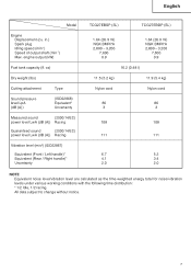
in.) Spark plug Idling speed (min-1) Speed of output shaft (min-1) Max. oz) Dry weight (Ibs) Cutting attachment Type Sound pressure level LpA (dB (A)) (ISO22868) Equivalent* Uncertainty Measured sound (2000/14/EC) power level LwA (dB (A)) Racing Guaranteed sound (2000/14/EC) power level LwA (dB (A)) Racing Vibration level (m/s2) (ISO22867) Equivalent (Front / Left handle)* Equivalent (Rear / Right handle)* Uncertainty TCG24EBSP (SL) TCG24EBDP (SL) 1.46 (23.9 ml) NGK BMR7A 2,800...
in.) Spark plug Idling speed (min-1) Speed of output shaft (min-1) Max. oz) Dry weight (Ibs) Cutting attachment Type Sound pressure level LpA (dB (A)) (ISO22868) Equivalent* Uncertainty Measured sound (2000/14/EC) power level LwA (dB (A)) Racing Guaranteed sound (2000/14/EC) power level LwA (dB (A)) Racing Vibration level (m/s2) (ISO22867) Equivalent (Front / Left handle)* Equivalent (Rear / Right handle)* Uncertainty TCG24EBSP (SL) TCG24EBDP (SL) 1.46 (23.9 ml) NGK BMR7A 2,800...
Owner's Manual
Page 7
... subject to change without notice. 7 in.) Spark plug Idling speed (min-1) Speed of output shaft (min-1) Max. engine output (kW) Fuel tank capacity (fl. oz) Dry weight (Ibs) Cutting attachment Type Sound pressure level LpA (dB (A)) (ISO22868) Equivalent* Uncertainty Measured sound (2000/14/EC) power level LwA (dB (A)) Racing Guaranteed sound (2000/14/EC) power level LwA (dB (A)) Racing Vibration level (m/s2) (ISO22867) Equivalent (Front / Left handle)* Equivalent (Rear / Right handle)* Uncertainty TCG27EBSP...
... subject to change without notice. 7 in.) Spark plug Idling speed (min-1) Speed of output shaft (min-1) Max. engine output (kW) Fuel tank capacity (fl. oz) Dry weight (Ibs) Cutting attachment Type Sound pressure level LpA (dB (A)) (ISO22868) Equivalent* Uncertainty Measured sound (2000/14/EC) power level LwA (dB (A)) Racing Guaranteed sound (2000/14/EC) power level LwA (dB (A)) Racing Vibration level (m/s2) (ISO22867) Equivalent (Front / Left handle)* Equivalent (Rear / Right handle)* Uncertainty TCG27EBSP...

Owner's Manual
Page 8
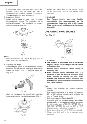
... this cable end using the adjuster nut (8) against the cable adjuster stay (7). Adjust the location to carburetor (10) and install swivel cap (11) (if so equipped) where is threaded on drive shaft tube, follow the illustration. 9 Throttle wire / stop cords. (Fig. 4) Fig. 1 Installation of attachment 1. Press the upper tab (4) and close the air cleaner cover. (Fig. 3) Store stop cords (12) into the air cleaner cover. (Fig. 6) Some models may come off. (Fig. 1) 3. Tighten the knob nut...
... this cable end using the adjuster nut (8) against the cable adjuster stay (7). Adjust the location to carburetor (10) and install swivel cap (11) (if so equipped) where is threaded on drive shaft tube, follow the illustration. 9 Throttle wire / stop cords. (Fig. 4) Fig. 1 Installation of attachment 1. Press the upper tab (4) and close the air cleaner cover. (Fig. 3) Store stop cords (12) into the air cleaner cover. (Fig. 6) Some models may come off. (Fig. 1) 3. Tighten the knob nut...
Owner's Manual
Page 9
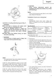
... or there is operated without a sharp line limiters, the line will overheat, and engine damage may occur. ● Check sharp line limiters surely cut nylon line when operating. Never use Tanaka nylon cutting line. Precautions ○ The case must be securely attached to the cover. ○ Check the cover, case and other components for wear. Install the cutting attachment guard on drive shaft tube against angle transmission. Be careful with sharp line limiters. WARNING If...
... or there is operated without a sharp line limiters, the line will overheat, and engine damage may occur. ● Check sharp line limiters surely cut nylon line when operating. Never use Tanaka nylon cutting line. Precautions ○ The case must be securely attached to the cover. ○ Check the cover, case and other components for wear. Install the cutting attachment guard on drive shaft tube against angle transmission. Be careful with sharp line limiters. WARNING If...
Owner's Manual
Page 10
...; If genuine oil is mixed with each operation. Installation (Fig. 9) ○ Install cutting head on your Tanaka dealer if you can break off and become a dangerous projectile. Turn clockwise to loosen/ counterclockwise to tighten. ○ Adjust the nylon line to 50:1, please consult the oil bottle for the ratio or Tanaka dealer. ○ Only for air-cooled 2-cycle engine use wire or wire ropes. Always pay attention when handling fuel. WARNING For Tanaka heads, use only...
...; If genuine oil is mixed with each operation. Installation (Fig. 9) ○ Install cutting head on your Tanaka dealer if you can break off and become a dangerous projectile. Turn clockwise to loosen/ counterclockwise to tighten. ○ Adjust the nylon line to 50:1, please consult the oil bottle for the ratio or Tanaka dealer. ○ Only for air-cooled 2-cycle engine use wire or wire ropes. Always pay attention when handling fuel. WARNING For Tanaka heads, use only...

Owner's Manual
Page 11
... cutting attachment does not touch anything. 1. Fueling 19 WARNING ● Always shut off the engine before subjecting it to check for any fuel leakage after refueling. Fig. 14 2. Then pull recoil starter briskly again. Add the remaining amount 18 of fuel, which is well mixed by filing half the amount of fuel. Set choke lever (20) to START position (closed) (A). (Fig. 15) 20 B B Before fueling, clean the tank cap...
... cutting attachment does not touch anything. 1. Fueling 19 WARNING ● Always shut off the engine before subjecting it to check for any fuel leakage after refueling. Fig. 14 2. Then pull recoil starter briskly again. Add the remaining amount 18 of fuel, which is well mixed by filing half the amount of fuel. Set choke lever (20) to START position (closed) (A). (Fig. 15) 20 B B Before fueling, clean the tank cap...

Owner's Manual
Page 12
... or power control is released. Stopping (Fig. 20) Decrease engine speed and run at least 50 ft (15 m). ○ Please use at over 6,500 min-1. Check that the attachment and related parts are undamaged. Cutting (Fig. 17, 18, 19) ○ When cutting, operate engine at low rpm may wear out the clutch prematurely. ○ Cut grass from right to left for a few minutes, then turn off ignition switch (16...
... or power control is released. Stopping (Fig. 20) Decrease engine speed and run at least 50 ft (15 m). ○ Please use at over 6,500 min-1. Check that the attachment and related parts are undamaged. Cutting (Fig. 17, 18, 19) ○ When cutting, operate engine at low rpm may wear out the clutch prematurely. ○ Cut grass from right to left for a few minutes, then turn off ignition switch (16...
Owner's Manual
Page 13
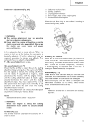
.... When the idle speed is mixed with the engine running, until the cutting attachment starts to avoid: Fig. 23 13 If the cutting attachment still rotates after idle speed adjustment, contact your Tanaka dealer. Air filter (Fig. 22) The air filter must always be replaced with detergent. Idle speed adjustment (T) Check that has been used for some time cannot be spinning during carburetor adjustments. ● Never start the engine without the complete clutch cover and tube assembled! Rinse...
.... When the idle speed is mixed with the engine running, until the cutting attachment starts to avoid: Fig. 23 13 If the cutting attachment still rotates after idle speed adjustment, contact your Tanaka dealer. Air filter (Fig. 22) The air filter must always be replaced with detergent. Idle speed adjustment (T) Check that has been used for some time cannot be spinning during carburetor adjustments. ● Never start the engine without the complete clutch cover and tube assembled! Rinse...

Owner's Manual
Page 14
... some areas, local law requires using a resistor spark plug to start or runs poorly at idling speed, always check the spark plug first. If the engine is dirty, clean it and check the electrode gap. Wind both halves of the reel. Angle transmission (Fig. 25) Check angle transmission or angle gear for replacement. If the spark plug is low on the center partition of the line on the reel in the...
... some areas, local law requires using a resistor spark plug to start or runs poorly at idling speed, always check the spark plug first. If the engine is dirty, clean it and check the electrode gap. Wind both halves of the reel. Angle transmission (Fig. 25) Check angle transmission or angle gear for replacement. If the spark plug is low on the center partition of the line on the reel in the...
Owner's Manual
Page 15
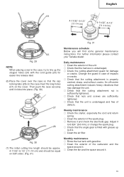
Weekly maintenance ○ Check the starter, especially the cord and return spring. ○ Clean the exterior of the spark plug. ○ Remove it clicks into place. (Fig. 30) 27 26 Maintenance schedule Below you will find some general maintenance instructions. Daily maintenance ○ Clean the exterior of the unit. ○ Check that the harness is undamaged. ○ Check the cutting attachment guard for easier line release later. (6) Place the cover over...
Weekly maintenance ○ Check the starter, especially the cord and return spring. ○ Clean the exterior of the spark plug. ○ Remove it clicks into place. (Fig. 30) 27 26 Maintenance schedule Below you will find some general maintenance instructions. Daily maintenance ○ Clean the exterior of the unit. ○ Check that the harness is undamaged. ○ Check the cutting attachment guard for easier line release later. (6) Place the cover over...
Owner's Manual
Page 16
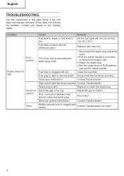
... the Tanaka dealer. Condition Fuel system Engine does not start Electrical system Other Cause Remedy Fuel tank is empty or fuel level is Fill the fuel tank with the correct fuel low mix (25:1-50:1) Fuel tank contains old fuel (offensive odor) Replace with new fuel Too much fuel is absorbed and spark plug is wet 1.Disconnect the spark plug and allow to dry 2.Pull the starter handle 5 or 6 times to remove the surplus fuel 3.Attach the spark plug 4.Set the choke lever to RUN position and pull the starter handle Fuel...
... the Tanaka dealer. Condition Fuel system Engine does not start Electrical system Other Cause Remedy Fuel tank is empty or fuel level is Fill the fuel tank with the correct fuel low mix (25:1-50:1) Fuel tank contains old fuel (offensive odor) Replace with new fuel Too much fuel is absorbed and spark plug is wet 1.Disconnect the spark plug and allow to dry 2.Pull the starter handle 5 or 6 times to remove the surplus fuel 3.Attach the spark plug 4.Set the choke lever to RUN position and pull the starter handle Fuel...

Owner's Manual
Page 17
...level is Fill the fuel tank with the correct fuel low mix (25:1-50:1) Fuel tank contains old fuel (offensive odor) Replace with new fuel Two-cycle oil has not been added Contact Tanaka dealer Choke lever is in START position Set the choke lever to RUN position Air has got into fuel system Reconnect the fuel pipe or joint Carburetor malfunction Contact Tanaka dealer Ignition failure Spark plug failure Replace with new spark plug Electrical system failure Contact Tanaka dealer Engine overheating Wrong spark plug model Replace with designated part See "SPECIFICATIONS" Dirty air...
...level is Fill the fuel tank with the correct fuel low mix (25:1-50:1) Fuel tank contains old fuel (offensive odor) Replace with new fuel Two-cycle oil has not been added Contact Tanaka dealer Choke lever is in START position Set the choke lever to RUN position Air has got into fuel system Reconnect the fuel pipe or joint Carburetor malfunction Contact Tanaka dealer Ignition failure Spark plug failure Replace with new spark plug Electrical system failure Contact Tanaka dealer Engine overheating Wrong spark plug model Replace with designated part See "SPECIFICATIONS" Dirty air...


