
Owner's Manual
Page 2
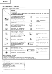
... unit. Fuel and oil mixture Keep all warnings and instructions in this unit. Careless or improper use the cutting attachment min-1 whose max rpm is correctly assembled and adjusted. • Start the unit and check the carburetor adjustment. Be careful of the unit may cause serious or fatal injury. Guaranteed Sound power 4 level Hot surface - Indicate handle location. See "MAINTENANCE". Choke - Do not use of thrown objects. Do not attach handle above...
... unit. Fuel and oil mixture Keep all warnings and instructions in this unit. Careless or improper use the cutting attachment min-1 whose max rpm is correctly assembled and adjusted. • Start the unit and check the carburetor adjustment. Be careful of the unit may cause serious or fatal injury. Guaranteed Sound power 4 level Hot surface - Indicate handle location. See "MAINTENANCE". Choke - Do not use of thrown objects. Do not attach handle above...
Owner's Manual
Page 3
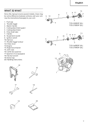
Use the instructions that apply to your unit. Starter handle 4. Drive shaft tube 7. Fuel cap 2. Cutting attachment 6. Ignition switch 10. Harness 5 11.Throttle trigger lockout 12.Choke lever 13. Engine 14.Angle transmission 15.Joint case 16.Combi box spanner 17.Spanner (if so equipped) 18.Hex bar wrench 19.Swivel cap 20.Handling instructions 10 16 6 4 13 7 9 11 3 1 2 TCG 24EBSP (SL) TCG 27EBSP (SL) 7 8 9 11 6 15 13 3 1 2 4 TCG 24EBDP (SL) TCG 27EBDP...
Use the instructions that apply to your unit. Starter handle 4. Drive shaft tube 7. Fuel cap 2. Cutting attachment 6. Ignition switch 10. Harness 5 11.Throttle trigger lockout 12.Choke lever 13. Engine 14.Angle transmission 15.Joint case 16.Combi box spanner 17.Spanner (if so equipped) 18.Hex bar wrench 19.Swivel cap 20.Handling instructions 10 16 6 4 13 7 9 11 3 1 2 TCG 24EBSP (SL) TCG 27EBSP (SL) 7 8 9 11 6 15 13 3 1 2 4 TCG 24EBDP (SL) TCG 27EBDP...

Owner's Manual
Page 4
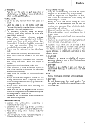
... fuel or the unit/machine or while using the unit/ machine. ○ Make sure the cutting attachment is properly installed and securely fastened. ○ Make sure the safety guard is properly attached. ○ Keep others away when making carburetor adjustments. ○ Use only accessories as a room or building. It is prolonged, take a break from water heaters, electric motors or switches, furnaces. Do not use...
... fuel or the unit/machine or while using the unit/ machine. ○ Make sure the cutting attachment is properly installed and securely fastened. ○ Make sure the safety guard is properly attached. ○ Keep others away when making carburetor adjustments. ○ Use only accessories as a room or building. It is prolonged, take a break from water heaters, electric motors or switches, furnaces. Do not use...
Owner's Manual
Page 5
... not covered in a dry place. ○ Make sure engine switch is shut off and any cutting attachments have to secure the machine during transport to prevent loss of injury from the cutting attachment. ○ Always carry a first-aid kit when operating any material other than grass and brush. ○ Clear the area to recommended procedures. ○ Disconnect the spark plug before performing maintenance...
... not covered in a dry place. ○ Make sure engine switch is shut off and any cutting attachments have to secure the machine during transport to prevent loss of injury from the cutting attachment. ○ Always carry a first-aid kit when operating any material other than grass and brush. ○ Clear the area to recommended procedures. ○ Disconnect the spark plug before performing maintenance...

Owner's Manual
Page 6
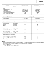
engine output (kW) Fuel tank capacity (fl. English SPECIFICATIONS Model Engine Displacement (cu. in.) Spark plug Idling speed (min-1) Speed of output shaft (min-1) Max. oz) Dry weight (Ibs) Cutting attachment Type Sound pressure level LpA (dB (A)) (ISO22868) Equivalent* Uncertainty Measured sound (2000/14/EC) power level LwA (dB (A)) Racing Guaranteed sound (2000/14/EC) power level LwA (dB (A)) Racing Vibration level (m/s2) (ISO22867) Equivalent (Front / Left handle)* Equivalent (Rear / Right handle)* Uncertainty TCG24EBSP (SL) TCG24EBDP (SL...
engine output (kW) Fuel tank capacity (fl. English SPECIFICATIONS Model Engine Displacement (cu. in.) Spark plug Idling speed (min-1) Speed of output shaft (min-1) Max. oz) Dry weight (Ibs) Cutting attachment Type Sound pressure level LpA (dB (A)) (ISO22868) Equivalent* Uncertainty Measured sound (2000/14/EC) power level LwA (dB (A)) Racing Guaranteed sound (2000/14/EC) power level LwA (dB (A)) Racing Vibration level (m/s2) (ISO22867) Equivalent (Front / Left handle)* Equivalent (Rear / Right handle)* Uncertainty TCG24EBSP (SL) TCG24EBDP (SL...
Owner's Manual
Page 7
... 7,600 0.9 16.2 (0.48 l) 11.5 (5.2 kg) 11.9 (5.4 kg) Nylon cord Nylon cord 86 86 3 3 108 108 111 111 6.7 5.3 4.1 3.4 2.0 2.0 NOTE Equivalent noise level/vibration level are calculated as the time-weighted energy total for noise/vibration levels under various working conditions with the following time distribution: * 1/2 Idle, 1/2 racing. in.) Spark plug Idling speed (min-1) Speed of output shaft (min-1) Max. engine output (kW) Fuel tank capacity (fl. English Model Engine Displacement (cu.
... 7,600 0.9 16.2 (0.48 l) 11.5 (5.2 kg) 11.9 (5.4 kg) Nylon cord Nylon cord 86 86 3 3 108 108 111 111 6.7 5.3 4.1 3.4 2.0 2.0 NOTE Equivalent noise level/vibration level are calculated as the time-weighted energy total for noise/vibration levels under various working conditions with the following time distribution: * 1/2 Idle, 1/2 racing. in.) Spark plug Idling speed (min-1) Speed of output shaft (min-1) Max. engine output (kW) Fuel tank capacity (fl. English Model Engine Displacement (cu.

Owner's Manual
Page 8
... comfortable position before operation. Connect throttle wire end (9) to carburetor (10) and install swivel cap (11) (if so equipped) where is threaded on your unit has handle location label on drive shaft tube, follow the illustration. 9 Throttle wire / stop cords. (Fig. 4) Fig. 1 Installation of tube and that the tube will not come with the angle towards the engine. Join the attachment in place of attachment 1. Make sure the lock pin...
... comfortable position before operation. Connect throttle wire end (9) to carburetor (10) and install swivel cap (11) (if so equipped) where is threaded on your unit has handle location label on drive shaft tube, follow the illustration. 9 Throttle wire / stop cords. (Fig. 4) Fig. 1 Installation of tube and that the tube will not come with the angle towards the engine. Join the attachment in place of attachment 1. Make sure the lock pin...
Owner's Manual
Page 9
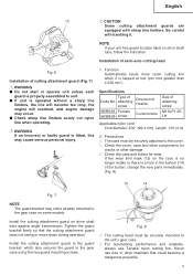
... reliability, always use wire or other damage. ○ Check the case and button for wear. Installation of semi-auto cutting head Fig. 6 Installation of the button, change the new parts immediately. (Fig. 8) 13 14 Fig. 7 NOTE The guard bracket may occur. ● Check sharp line limiters surely cut nylon line when operating. Tighten the guard bracket firmly so that could become too long, the engine will overheat...
... reliability, always use wire or other damage. ○ Check the case and button for wear. Installation of semi-auto cutting head Fig. 6 Installation of the button, change the new parts immediately. (Fig. 8) 13 14 Fig. 7 NOTE The guard bracket may occur. ● Check sharp line limiters surely cut nylon line when operating. Tighten the guard bracket firmly so that could become too long, the engine will overheat...
Owner's Manual
Page 10
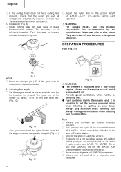
..., you need assistance. 3. They can extend the nylon line by the manufacturer. Always run the engine on gear case of the gear case in a separate clean container. 10 OPERATING PROCEDURES Fuel (Fig. 12) 15 Fig. 9 NOTE ○ Press the stopper pin (15) of grass trimmers/brush cutters. Installation (Fig. 9) ○ Install cutting head on fuel, which is possible to lock the cutter holder. 4. WARNING For Tanaka heads, use (JASO FC GRADE OIL or...
..., you need assistance. 3. They can extend the nylon line by the manufacturer. Always run the engine on gear case of the gear case in a separate clean container. 10 OPERATING PROCEDURES Fuel (Fig. 12) 15 Fig. 9 NOTE ○ Press the stopper pin (15) of grass trimmers/brush cutters. Installation (Fig. 9) ○ Install cutting head on fuel, which is possible to lock the cutter holder. 4. WARNING For Tanaka heads, use (JASO FC GRADE OIL or...

Owner's Manual
Page 11
... ft (3 m) from the fueling area before starting , make sure the cutting attachment does not touch anything. 1. Add the remaining amount 18 of oil. When you hear the engine want to start, return choke lever to RUN position (open the fuel tank, when filling up before subjecting it to 4. 5. Then pull recoil starter briskly again. Pull recoil starter briskly, taking care to keep the handle in your grasp...
... ft (3 m) from the fueling area before starting , make sure the cutting attachment does not touch anything. 1. Add the remaining amount 18 of oil. When you hear the engine want to start, return choke lever to RUN position (open the fuel tank, when filling up before subjecting it to 4. 5. Then pull recoil starter briskly again. Pull recoil starter briskly, taking care to keep the handle in your grasp...

Owner's Manual
Page 12
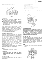
... cutting attachment should strike against stones or other debris, stop engine and attachment and remove them. Stopping (Fig. 20) Decrease engine speed and run at over 6,500 min-1. Extended time of use at low rpm may wear out the clutch prematurely. ○ Cut grass from right to left. Semi-auto cutting head ○ When cutting, operate engine at an idle for efficient cutting. Cutting (Fig. 17, 18, 19) ○ When cutting, operate engine...
... cutting attachment should strike against stones or other debris, stop engine and attachment and remove them. Stopping (Fig. 20) Decrease engine speed and run at over 6,500 min-1. Extended time of use at low rpm may wear out the clutch prematurely. ○ Cut grass from right to left. Semi-auto cutting head ○ When cutting, operate engine at an idle for efficient cutting. Cutting (Fig. 17, 18, 19) ○ When cutting, operate engine...
Owner's Manual
Page 13
... warm water with the engine running, until the cutting attachment stops. Fig. 21 21 WARNING ● The cutting attachment may be replaced. An air filter that the air filter is mixed with a new one adjustment possibility: T = Idle speed adjustment screw. In the carburetor, fuel is clean. Idle speed adjustment (T) Check that has been used for some time cannot be spinning during carburetor adjustments. ● Never start the engine without the complete clutch cover and tube assembled! Squeeze, do not wring...
... warm water with the engine running, until the cutting attachment stops. Fig. 21 21 WARNING ● The cutting attachment may be replaced. An air filter that the air filter is mixed with a new one adjustment possibility: T = Idle speed adjustment screw. In the carburetor, fuel is clean. Idle speed adjustment (T) Check that has been used for some time cannot be spinning during carburetor adjustments. ● Never start the engine without the complete clutch cover and tube assembled! Squeeze, do not wring...

Owner's Manual
Page 14
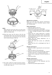
... of spark plug for grease level about 100 operation hours or earlier if the electrodes are badly eroded. 0.024" (0.6 mm) Semi-auto cutting head Nylon line replacement (1) Remove the case (22) by removing the grease filler plug on the flanks of angle transmission. The spark plug should be seen on the side of the gears, fill the transmission with resistor spark plug, use same type of the line through the cord guide...
... of spark plug for grease level about 100 operation hours or earlier if the electrodes are badly eroded. 0.024" (0.6 mm) Semi-auto cutting head Nylon line replacement (1) Remove the case (22) by removing the grease filler plug on the flanks of angle transmission. The spark plug should be seen on the side of the gears, fill the transmission with resistor spark plug, use same type of the line through the cord guide...
Owner's Manual
Page 15
.... ○ Check the cutting attachment guard for easier line release later. (6) Place the cover over the case so that the unit is undamaged and free of the spark plug. ○ Remove it clicks into place. (Fig. 30) 27 26 Maintenance schedule Below you will find some general maintenance instructions. Daily maintenance ○ Clean the exterior of impacts or cracks. ○ Check that the angle gear is...
.... ○ Check the cutting attachment guard for easier line release later. (6) Place the cover over the case so that the unit is undamaged and free of the spark plug. ○ Remove it clicks into place. (Fig. 30) 27 26 Maintenance schedule Below you will find some general maintenance instructions. Daily maintenance ○ Clean the exterior of impacts or cracks. ○ Check that the angle gear is...
Owner's Manual
Page 16
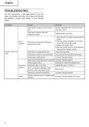
... tool does not operate normally. Condition Fuel system Engine does not start Electrical system Other Cause Remedy Fuel tank is empty or fuel level is Fill the fuel tank with the correct fuel low mix (25:1-50:1) Fuel tank contains old fuel (offensive odor) Replace with new fuel Too much fuel is absorbed and spark plug is wet 1.Disconnect the spark plug and allow to dry 2.Pull the starter handle 5 or 6 times to remove the surplus fuel 3.Attach the spark plug 4.Set the choke lever to RUN position and pull...
... tool does not operate normally. Condition Fuel system Engine does not start Electrical system Other Cause Remedy Fuel tank is empty or fuel level is Fill the fuel tank with the correct fuel low mix (25:1-50:1) Fuel tank contains old fuel (offensive odor) Replace with new fuel Too much fuel is absorbed and spark plug is wet 1.Disconnect the spark plug and allow to dry 2.Pull the starter handle 5 or 6 times to remove the surplus fuel 3.Attach the spark plug 4.Set the choke lever to RUN position and pull...

Owner's Manual
Page 17
...level is Fill the fuel tank with the correct fuel low mix (25:1-50:1) Fuel tank contains old fuel (offensive odor) Replace with new fuel Two-cycle oil has not been added Contact Tanaka dealer Choke lever is in START position Set the choke lever to RUN position Air has got into fuel system Reconnect the fuel pipe or joint Carburetor malfunction Contact Tanaka dealer Ignition failure Spark plug failure Replace with new spark plug Electrical system failure Contact Tanaka dealer Engine overheating Wrong spark plug model Replace with designated part See "SPECIFICATIONS" Dirty air...
...level is Fill the fuel tank with the correct fuel low mix (25:1-50:1) Fuel tank contains old fuel (offensive odor) Replace with new fuel Two-cycle oil has not been added Contact Tanaka dealer Choke lever is in START position Set the choke lever to RUN position Air has got into fuel system Reconnect the fuel pipe or joint Carburetor malfunction Contact Tanaka dealer Ignition failure Spark plug failure Replace with new spark plug Electrical system failure Contact Tanaka dealer Engine overheating Wrong spark plug model Replace with designated part See "SPECIFICATIONS" Dirty air...
Parts List
Page 4
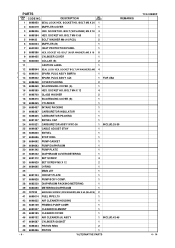
... INTAKE PACKING 1 21 6698387 CARBURETOR INSULATOR 1 22 6698405 CARBURETOR PACKING 1 23 6691337 SWIVEL CAP 1 24 6600321 CARBURETOR ASS'Y WYC-36 1 INCLUD.25-39 25 6699287 CABLE ADJUST STAY 1 26 6696830 SWIVEL 1 27 6684696 STOP RING 1 28 6684692 PUMP GASKET 1 29 6684693 PUMP DIAPHRAGM 1 30 6691242 PUMP PLATE 1 31 6685222 DIAPHRAGM COVER-METERING 1 32 6691312 SET SCREW 4 33 6696829 SET SCREW M3 X 12 2 34 6684695...
... INTAKE PACKING 1 21 6698387 CARBURETOR INSULATOR 1 22 6698405 CARBURETOR PACKING 1 23 6691337 SWIVEL CAP 1 24 6600321 CARBURETOR ASS'Y WYC-36 1 INCLUD.25-39 25 6699287 CABLE ADJUST STAY 1 26 6696830 SWIVEL 1 27 6684696 STOP RING 1 28 6684692 PUMP GASKET 1 29 6684693 PUMP DIAPHRAGM 1 30 6691242 PUMP PLATE 1 31 6685222 DIAPHRAGM COVER-METERING 1 32 6691312 SET SCREW 4 33 6696829 SET SCREW M3 X 12 2 34 6684695...
Parts List
Page 5
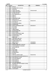
... 6600323 MUFFLER HEAT COVER 1 76 6600325 TAPPING SCREW D4 X 10 2 * 77 6600327 MARK PLATE (T) 1 FOR EUROPE * 78 6699000 PRIMER LABEL 1 FOR EUROPE 91 6699195 MACHINE SCREW M5 X 20 (BLACK) 2 92 6699194 P TIGTH SCREW D4 X 20 (BLACK) 4 93 6699197 SWITCH WIRE SET 1 94 6699196 NUT M5 2 95 6699192 STOP LEVER 1 96 6699191 LONG LEVER 1 97 6699193 RETURN SPRING 1 98 6699190 STAY SET 1 99 6699133 THROTTLE LEVER (A) ASS...
... 6600323 MUFFLER HEAT COVER 1 76 6600325 TAPPING SCREW D4 X 10 2 * 77 6600327 MARK PLATE (T) 1 FOR EUROPE * 78 6699000 PRIMER LABEL 1 FOR EUROPE 91 6699195 MACHINE SCREW M5 X 20 (BLACK) 2 92 6699194 P TIGTH SCREW D4 X 20 (BLACK) 4 93 6699197 SWITCH WIRE SET 1 94 6699196 NUT M5 2 95 6699192 STOP LEVER 1 96 6699191 LONG LEVER 1 97 6699193 RETURN SPRING 1 98 6699190 STAY SET 1 99 6699133 THROTTLE LEVER (A) ASS...

Parts List
Page 6
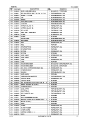
... (A) 1 164 6684852 LEVEL MARK 1 165 6699462 DRIVE SHAFT (A) 1 166 6696493 HANGER 1 * 167 6699448 LOOP HANDLE (W/BARRIER) 1 FOR EUROPE * 168 6699449 LOOP HANDLE 1 FOR USA 169 6684828 CAP NUT 6 1 170 6684817 JOINT CASE 1 * 171 6699439 GEAR CASE ASS'Y (4BB) 1 INCLUD.172-181 FOR EUROPE (SL) - 6 - *ALTERNATIVE PARTS 4 - 14 CODE NO. 111 6696469 STEP BOLT DESCRIPTION NO. BOLT M5 X 12 1 155 6698884 SPRING WASHER M5...
... (A) 1 164 6684852 LEVEL MARK 1 165 6699462 DRIVE SHAFT (A) 1 166 6696493 HANGER 1 * 167 6699448 LOOP HANDLE (W/BARRIER) 1 FOR EUROPE * 168 6699449 LOOP HANDLE 1 FOR USA 169 6684828 CAP NUT 6 1 170 6684817 JOINT CASE 1 * 171 6699439 GEAR CASE ASS'Y (4BB) 1 INCLUD.172-181 FOR EUROPE (SL) - 6 - *ALTERNATIVE PARTS 4 - 14 CODE NO. 111 6696469 STEP BOLT DESCRIPTION NO. BOLT M5 X 12 1 155 6698884 SPRING WASHER M5...
Parts List
Page 7
...) * 173 6695414 SCREW 5 X 12/W.S 1 FOR USA,EUROPE (SL) * 174 6600005 CAP 1 FOR USA,EUROPE (SL) * 175 6600006 SPRING 1 FOR USA,EUROPE (SL) * 176 6684737 BOLT (W/PLUS) M6 X 8 1 FOR USA,EUROPE (SL) * 177 6600007 LOCK PIN 1 FOR USA,EUROPE (SL) * 178 6699441 CUTTER HOLDER (A) 1 FOR EUROPE (SL) * 179 6698659 CUTTER HOLDER (B) 1 FOR EUROPE (SL) * 180 6699188 NUT COVER 1 FOR...
...) * 173 6695414 SCREW 5 X 12/W.S 1 FOR USA,EUROPE (SL) * 174 6600005 CAP 1 FOR USA,EUROPE (SL) * 175 6600006 SPRING 1 FOR USA,EUROPE (SL) * 176 6684737 BOLT (W/PLUS) M6 X 8 1 FOR USA,EUROPE (SL) * 177 6600007 LOCK PIN 1 FOR USA,EUROPE (SL) * 178 6699441 CUTTER HOLDER (A) 1 FOR EUROPE (SL) * 179 6698659 CUTTER HOLDER (B) 1 FOR EUROPE (SL) * 180 6699188 NUT COVER 1 FOR...


