

Parts List
Page 6
... 1 10 6698386 HEX. SOCKET BOLT (W/WASHERS) M5 5 24 6698405 CARBURETOR PACKING 1 25 6691337 SWIVEL CAP 1 26 6696550 CARBURETOR ASS'Y WYC-22 1 INCLUD.27-41 27 6699287 CABLE ADJUST STAY 1 28 6696830 SWIVEL 1 29 6684696 STOP RING 1 30 6684692 PUMP GASKET 1 31 6684693 PUMP DIAPHRAGM 1 32 6691242 PUMP PLATE 1 33 6685222 DIAPHRAGM COVER-METERING 1 34 6691312 SET SCREW 4 35 6696829 SET SCREW M3 X 12 2 36...
... 1 10 6698386 HEX. SOCKET BOLT (W/WASHERS) M5 5 24 6698405 CARBURETOR PACKING 1 25 6691337 SWIVEL CAP 1 26 6696550 CARBURETOR ASS'Y WYC-22 1 INCLUD.27-41 27 6699287 CABLE ADJUST STAY 1 28 6696830 SWIVEL 1 29 6684696 STOP RING 1 30 6684692 PUMP GASKET 1 31 6684693 PUMP DIAPHRAGM 1 32 6691242 PUMP PLATE 1 33 6685222 DIAPHRAGM COVER-METERING 1 34 6691312 SET SCREW 4 35 6696829 SET SCREW M3 X 12 2 36...

Parts List
Page 7
... EUROPE (LB) * 78 6684675 RECOIL SPRING 1 FOR EUROPE (LB) * 79 STARTER CASE COM. 1 FOR EUROPE (LB) * 80 6693168 ROPE 1 FOR EUROPE (LB) * 81 6693227 STARTER HANDLE 1 FOR EUROPE (LB) * 82 6696572 RECOIL STARTER BODY ASS'Y 1 INCLUD.76-81 FOR EUROPE (LB) * 83 6685068 MACHINE SCREW (W/SP. BOLT (W/SP.WASHER) M5 X 12 1 9 - 15 *ALTERNATIVE PARTS - 7 - CODE NO. WASHER) M4 X 12 3 FOR...
... EUROPE (LB) * 78 6684675 RECOIL SPRING 1 FOR EUROPE (LB) * 79 STARTER CASE COM. 1 FOR EUROPE (LB) * 80 6693168 ROPE 1 FOR EUROPE (LB) * 81 6693227 STARTER HANDLE 1 FOR EUROPE (LB) * 82 6696572 RECOIL STARTER BODY ASS'Y 1 INCLUD.76-81 FOR EUROPE (LB) * 83 6685068 MACHINE SCREW (W/SP. BOLT (W/SP.WASHER) M5 X 12 1 9 - 15 *ALTERNATIVE PARTS - 7 - CODE NO. WASHER) M4 X 12 3 FOR...

Parts List
Page 8
... PUMP FILTER 1 141 6696949 CLIP 1 * 142 6698716 FUEL PIPE 1 * 142 6698932 FUEL PIPE L180 1 FOR USA 143 6696476 FUEL PIPE (PINK) 1 144 6697846 RETURN GROMMET 1 145 6698931 FUEL GROMMET 1 146 6698402 FUEL TANK CAP ASS'Y 1 INCLUD.147 147 6698732 TANK CAP CHAIN 1 * 171 323837 TAPPING SCREW (W/FLANGE) D4 X 30 1 FOR EUROPE (S) - 8 - *ALTERNATIVE PARTS 9 - 15 USED 2 REMARKS TCG 22EAP2 108 6699159 FAN CASE (VERMILION) 1 * 109 6699199 CLUTCH SHAFT...
... PUMP FILTER 1 141 6696949 CLIP 1 * 142 6698716 FUEL PIPE 1 * 142 6698932 FUEL PIPE L180 1 FOR USA 143 6696476 FUEL PIPE (PINK) 1 144 6697846 RETURN GROMMET 1 145 6698931 FUEL GROMMET 1 146 6698402 FUEL TANK CAP ASS'Y 1 INCLUD.147 147 6698732 TANK CAP CHAIN 1 * 171 323837 TAPPING SCREW (W/FLANGE) D4 X 30 1 FOR EUROPE (S) - 8 - *ALTERNATIVE PARTS 9 - 15 USED 2 REMARKS TCG 22EAP2 108 6699159 FAN CASE (VERMILION) 1 * 109 6699199 CLUTCH SHAFT...

Parts List
Page 9
.... CODE NO. BOLT M5 X 30 (10 PCS.) 1 FOR EUROPE (S,SL,SLD),USA (SL,SLD) * 198 6698794 COVER 1 FOR EUROPE (S,SL,SLD),USA (SL,SLD) 199 NYLON CORD 1 200 6698795 SET SCREW 1 * 201 6698796 REEL 1 FOR EUROPE (S,SL,SLD),USA (SL,SLD) * 202 6698797 RETURN SPRING 1 FOR EUROPE (S,SL,SLD),USA (SL,SLD) 203 6698798 BUTTON 1 204 6698799 CORD GUIDE...
.... CODE NO. BOLT M5 X 30 (10 PCS.) 1 FOR EUROPE (S,SL,SLD),USA (SL,SLD) * 198 6698794 COVER 1 FOR EUROPE (S,SL,SLD),USA (SL,SLD) 199 NYLON CORD 1 200 6698795 SET SCREW 1 * 201 6698796 REEL 1 FOR EUROPE (S,SL,SLD),USA (SL,SLD) * 202 6698797 RETURN SPRING 1 FOR EUROPE (S,SL,SLD),USA (SL,SLD) 203 6698798 BUTTON 1 204 6698799 CORD GUIDE...
Manual
Page 2
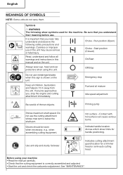
... Fuel and oil mixture Idle speed adjustment Be careful of the unit may cause serious or fatal injury. Hot surface - Indicate handle location. Use anti-slip and sturdy footwear. See "MAINTENANCE". 2 On/Start Always wear eye, head and ear protectors when using your machine • Read the manual carefully. • Check that the cutting equipment is below the shaft rpm. Emergency stop the engine and cutting attachment immediately. Do not use...
... Fuel and oil mixture Idle speed adjustment Be careful of the unit may cause serious or fatal injury. Hot surface - Indicate handle location. Use anti-slip and sturdy footwear. See "MAINTENANCE". 2 On/Start Always wear eye, head and ear protectors when using your machine • Read the manual carefully. • Check that the cutting equipment is below the shaft rpm. Emergency stop the engine and cutting attachment immediately. Do not use...
Manual
Page 3
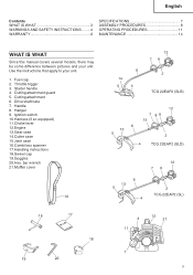
Use the instructions that apply to your unit. Fuel cap 2. Cutting attachment 6. Hanger 9. Goggles 20.Hex. Drive shaft tube 7. Ignition switch 10.Harness (if so equipped) 11.Choke lever 12. English Contents WHAT IS WHAT 3 WARNINGS AND SAFETY INSTRUCTIONS ........ 4 WARRANTY 6 SPECIFICATIONS 7 ASSEMBLY PROCEDURES 8 OPERATING PROCEDURES 11 MAINTENANCE 14 WHAT IS WHAT Since this manual covers several models, there may be some difference between pictures and your unit. 1. Starter handle 4. Engine 13.Gear case 14...
Use the instructions that apply to your unit. Fuel cap 2. Cutting attachment 6. Hanger 9. Goggles 20.Hex. Drive shaft tube 7. Ignition switch 10.Harness (if so equipped) 11.Choke lever 12. English Contents WHAT IS WHAT 3 WARNINGS AND SAFETY INSTRUCTIONS ........ 4 WARRANTY 6 SPECIFICATIONS 7 ASSEMBLY PROCEDURES 8 OPERATING PROCEDURES 11 MAINTENANCE 14 WHAT IS WHAT Since this manual covers several models, there may be some difference between pictures and your unit. 1. Starter handle 4. Engine 13.Gear case 14...
Manual
Page 4
... fuel leaks and make sure the cutting attachment has stopped before each use . Remove safety equipment immediately upon shutting off engine. ○ Wear head protection. ○ Never start the engine if there are any symptoms of the above shoulder length. ○ Do not operate this product contains chemical known to the State of oil and fuel. ○ Keep hands away from time to time...
... fuel leaks and make sure the cutting attachment has stopped before each use . Remove safety equipment immediately upon shutting off engine. ○ Wear head protection. ○ Never start the engine if there are any symptoms of the above shoulder length. ○ Do not operate this product contains chemical known to the State of oil and fuel. ○ Keep hands away from time to time...

Manual
Page 5
... electrical cables or gas pipes are properly attached. Do not remove the fuel cap during work area, or inspecting, adjusting or exchanging the unit's cutting attachments, accessories, etc., be thrown or become entangled in the cutting attachment. ○ For respiratory protection, wear an aerosol protection mask when cutting the grass after pulling the starter handle. ○ Always keep the engine on the ground when running . ○ Keep cutting attachment below knee level...
... electrical cables or gas pipes are properly attached. Do not remove the fuel cap during work area, or inspecting, adjusting or exchanging the unit's cutting attachments, accessories, etc., be thrown or become entangled in the cutting attachment. ○ For respiratory protection, wear an aerosol protection mask when cutting the grass after pulling the starter handle. ○ Always keep the engine on the ground when running . ○ Keep cutting attachment below knee level...
Manual
Page 6
... remove the cutting attachment or place the blade cover over the blade. ○ You have it inspected and repaired. Failure to recommended procedures. ○ Disconnect the spark plug before storing or transporting. WARNING Improper maintenance could lead to cool, empty the fuel tank, and secure the unit/machine before performing maintenance except for carburetor adjustments. ○ Keep others away when making carburetor adjustments. ○ Use only genuine Tanaka replacement parts as...
... remove the cutting attachment or place the blade cover over the blade. ○ You have it inspected and repaired. Failure to recommended procedures. ○ Disconnect the spark plug before storing or transporting. WARNING Improper maintenance could lead to cool, empty the fuel tank, and secure the unit/machine before performing maintenance except for carburetor adjustments. ○ Keep others away when making carburetor adjustments. ○ Use only genuine Tanaka replacement parts as...
Manual
Page 8
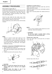
... has handle location label (6) on the drive shaft tube, turn drive shaft by the cutter mounting end clockwise or counter-clockwise. Some models may come off. (Fig. 2) 3. Throttle wire / stop cords. (Fig. 5) Fig. 2 CAUTION ● When you pull and release the lock pin (3), always make sure it . 2. Tighten the knob nut (5) securely. (Fig. 2) 3 5 4 Fig. 4 Connect stop cord Press the upper tab (7) and open the air cleaner cover. (Fig. 4) 7 Installation of...
... has handle location label (6) on the drive shaft tube, turn drive shaft by the cutter mounting end clockwise or counter-clockwise. Some models may come off. (Fig. 2) 3. Throttle wire / stop cords. (Fig. 5) Fig. 2 CAUTION ● When you pull and release the lock pin (3), always make sure it . 2. Tighten the knob nut (5) securely. (Fig. 2) 3 5 4 Fig. 4 Connect stop cord Press the upper tab (7) and open the air cleaner cover. (Fig. 4) 7 Installation of...
Manual
Page 9
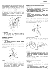
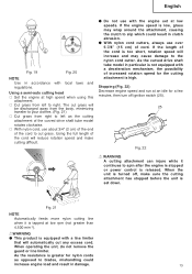
... the drive shaft tube. (Fig. 7) Adjust the length of the harness for easy operation of the tool. Attach the harness hook (16) to unit. ● If an incorrect or faulty guard is fitted, this cable end using the adjuster nut (11) against screw (15) when the throttle is closed. Installation of cuttingt attachment guard WARNING ● Do not start or operate unit unless each guard is properly assembled to...
... the drive shaft tube. (Fig. 7) Adjust the length of the harness for easy operation of the tool. Attach the harness hook (16) to unit. ● If an incorrect or faulty guard is fitted, this cable end using the adjuster nut (11) against screw (15) when the throttle is closed. Installation of cuttingt attachment guard WARNING ● Do not start or operate unit unless each guard is properly assembled to...
Manual
Page 10
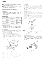
... be securely attached to the unit's gear case/cutter case. ○ If the cutting head does not feed cutting line properly, check that the nylon line and all components are properly installed. attaching screw 6696454 Female screw 6696597 Female screw Direction of rotation Counterclockwise Clockwise Size of the button, change the new parts immediately. (Fig. 10) 22 23 Fig. 11 NOTE For curved drive shaft tube models, the mounting nut is...
... be securely attached to the unit's gear case/cutter case. ○ If the cutting head does not feed cutting line properly, check that the nylon line and all components are properly installed. attaching screw 6696454 Female screw 6696597 Female screw Direction of rotation Counterclockwise Clockwise Size of the button, change the new parts immediately. (Fig. 10) 22 23 Fig. 11 NOTE For curved drive shaft tube models, the mounting nut is...
Manual
Page 11
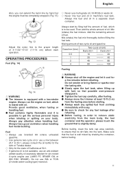
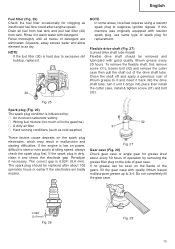
... a two-stroke engine. Always run the engine on your body. Always have good ventilation when handling fuel inside building. Fuel ○ Always use branded 89 octane unleaded gasoline. ○ Use genuine two-cycle oil or use a mix between 25:1 to 50:1, please consult the oil bottle for the ratio or Tanaka dealer. ○ Only for the state of fuel, which is to remove static electricity from the main...
... a two-stroke engine. Always run the engine on your body. Always have good ventilation when handling fuel inside building. Fuel ○ Always use branded 89 octane unleaded gasoline. ○ Use genuine two-cycle oil or use a mix between 25:1 to 50:1, please consult the oil bottle for the ratio or Tanaka dealer. ○ Only for the state of fuel, which is to remove static electricity from the main...
Manual
Page 12
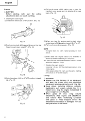
... the engine is idling. 2. Cutting WARNING ● Always use the same starting procedure as early abrasion of the starting , make sure the cutting attachment does not touch anything. 1. Continuing operation with grass or vines wrapped around attachment, stop engine and attachment and remove them. English Starting CAUTION Before starting procedure for a cold engine. Starting the cold engine (1) Set ignition switch (25) to ON position. (Fig. 15) (4) Pull recoil starter briskly, taking care to keep the handle...
... the engine is idling. 2. Cutting WARNING ● Always use the same starting procedure as early abrasion of the starting , make sure the cutting attachment does not touch anything. 1. Continuing operation with grass or vines wrapped around attachment, stop engine and attachment and remove them. English Starting CAUTION Before starting procedure for a cold engine. Starting the cold engine (1) Set ignition switch (25) to ON position. (Fig. 15) (4) Pull recoil starter briskly, taking care to keep the handle...
Manual
Page 13
... in clutch abrasion. ● With nylon cord cutters, always use about 3/4" (2 cm) of the end of cord. As the resistance is greater for a few minutes, then turn off ignition switch (25). 25 Fig. 22 WARNING A cutting attachment can injure while it is high. When operating the unit, do not remove the guard or line limiter. Stopping (Fig. 22) Decrease engine speed and run at high speed when using this attachment. ○ Cut grass...
... in clutch abrasion. ● With nylon cord cutters, always use about 3/4" (2 cm) of the end of cord. As the resistance is greater for a few minutes, then turn off ignition switch (25). 25 Fig. 22 WARNING A cutting attachment can injure while it is high. When operating the unit, do not remove the guard or line limiter. Stopping (Fig. 22) Decrease engine speed and run at high speed when using this attachment. ○ Cut grass...
Manual
Page 14
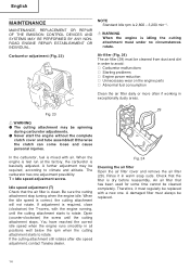
... time cannot be replaced with a new one adjustment possibility: T = Idle speed adjustment screw. Therefore, it in all positions well below the rpm when the cutting attachment starts to rotate. Idle speed adjustment (T) Check that the filter is correct, the cutting attachment will not rotate. When the engine is test run at the factory, the carburetor is idling the cutting attachment must always be spinning during carburetor adjustments. ● Never start the engine without the complete clutch cover and tube assembled...
... time cannot be replaced with a new one adjustment possibility: T = Idle speed adjustment screw. Therefore, it in all positions well below the rpm when the cutting attachment starts to rotate. Idle speed adjustment (T) Check that the filter is correct, the cutting attachment will not rotate. When the engine is test run at the factory, the carburetor is idling the cutting attachment must always be spinning during carburetor adjustments. ● Never start the engine without the complete clutch cover and tube assembled...
Manual
Page 15
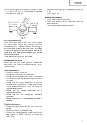
... removed and lubricated with detergent. If the engine is hard due to excessive dirt buildup, replace it drops into the drive shaft tube, turn it unit it . 30 NOTE In some areas, local law requires using a resistor spark plug to suppress ignition signals. The spark plug should be replaced after about every 50 hours of operation by : ○ An incorrect carburetor setting ○ Wrong fuel mixture (too much oil...
... removed and lubricated with detergent. If the engine is hard due to excessive dirt buildup, replace it drops into the drive shaft tube, turn it unit it . 30 NOTE In some areas, local law requires using a resistor spark plug to suppress ignition signals. The spark plug should be replaced after about every 50 hours of operation by : ○ An incorrect carburetor setting ○ Wrong fuel mixture (too much oil...
Manual
Page 17
... maintenance ○ Clean the exterior of the spark plug. ○ Remove the spark plug and check the electrode gap. Adjust it stops. Start and let engine run until it to distribute oil. Weekly maintenance ○ Check the starter, especially the cord and return spring. ○ Clean the exterior of the unit. ○ Check that the cutting attachment is undamaged. ○ Check the cutting attachment guard for damage or cracks. Change the guard in a dry area. An off-centre cutting attachment induces...
... maintenance ○ Clean the exterior of the spark plug. ○ Remove the spark plug and check the electrode gap. Adjust it stops. Start and let engine run until it to distribute oil. Weekly maintenance ○ Check the starter, especially the cord and return spring. ○ Clean the exterior of the unit. ○ Check that the cutting attachment is undamaged. ○ Check the cutting attachment guard for damage or cracks. Change the guard in a dry area. An off-centre cutting attachment induces...

Manual
Page 18
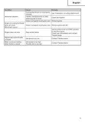
... Set the choke lever to RUN position Reconnect the fuel pipe or joint Contact Tanaka dealer Replace with new spark plug Contact Tanaka dealer Replace with designated part See "SPECIFICATIONS" Clean Clean Contact Tanaka dealer 18 If this does not remedy the problem, consult your dealer or the Tanaka dealer. Condition Fuel system Engine does not start Electrical system Other Fuel system Engine starts but cuts out straightaway Engine is apt to cut out Electrical system Other Cause Fuel tank is empty or fuel level...
... Set the choke lever to RUN position Reconnect the fuel pipe or joint Contact Tanaka dealer Replace with new spark plug Contact Tanaka dealer Replace with designated part See "SPECIFICATIONS" Clean Clean Contact Tanaka dealer 18 If this does not remedy the problem, consult your dealer or the Tanaka dealer. Condition Fuel system Engine does not start Electrical system Other Fuel system Engine starts but cuts out straightaway Engine is apt to cut out Electrical system Other Cause Fuel tank is empty or fuel level...
Manual
Page 19
... Engine stops when throttle is closed Blade continues rotating when throttle is closed Cause Remedy Cutting attachment is not properly installed See "Installation of cutting attachment" Handle, handle bracket or other fastening part is loose Check and tighten Grass is wrapped round gear case Remove grass Grass is wrapped round gear case Remove grass and dirt Stop switch failure Idle speed is too low Idle speed is too high Throttle wire is too taut Set the choke lever to START position to stop the engine Cease use...
... Engine stops when throttle is closed Blade continues rotating when throttle is closed Cause Remedy Cutting attachment is not properly installed See "Installation of cutting attachment" Handle, handle bracket or other fastening part is loose Check and tighten Grass is wrapped round gear case Remove grass Grass is wrapped round gear case Remove grass and dirt Stop switch failure Idle speed is too low Idle speed is too high Throttle wire is too taut Set the choke lever to START position to stop the engine Cease use...


