Parts List
Page 1
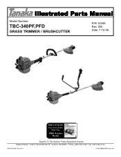
Illustrated Parts Manual Model Number: TBC-340PF,PFD GRASS TRIMMER / BRUSHCUTTER P/N 32348 Rev 000 Date 7-15-08 Supplier To The Outdoor Power Equipment Industry Tanaka America • 1028 4th Street SW Ste "B" • Auburn, WA 98001 • Phone: (253) 333-1200 • Fax: (253) 333-1212 www.tanaka-usa.com custsvc@tanaka-usa.com
Illustrated Parts Manual Model Number: TBC-340PF,PFD GRASS TRIMMER / BRUSHCUTTER P/N 32348 Rev 000 Date 7-15-08 Supplier To The Outdoor Power Equipment Industry Tanaka America • 1028 4th Street SW Ste "B" • Auburn, WA 98001 • Phone: (253) 333-1200 • Fax: (253) 333-1212 www.tanaka-usa.com custsvc@tanaka-usa.com
Parts List
Page 2
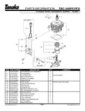
PARTS INFORMATION TBC-340PF,PFD CYLINDER, PISTON, CRANKSHAFT, IGNITION • FIGURE 1 ITEM PART NUMBER DESCRIPTION 1-1 15701570900 CAP,SPARK PLUG,ASSEMBLY 1-2 0181161021 PLUG,SPARK 1-6 0010725090 CYLINDER SET 1-7 99461050164 BOLT,HEX,5X16,S 1-9 0170725020 GASKET,CYLINDER 1-11 04101730200 RING,PISTON 1-12 0300703091 PISTON SET 1-13 03900000201 CIRCLIP,PISTON PIN 1-14 03701400200 PIN,PISTON 1-16 0460703A81 CRANKSHAFT 1-17 99962091325 BEARING,NEEDLE,F-910 1-18 06810100200 KEY,WOODRUFF,3X13X4.5 1-44 1780703B80 CORD,STOP B 1-46...
PARTS INFORMATION TBC-340PF,PFD CYLINDER, PISTON, CRANKSHAFT, IGNITION • FIGURE 1 ITEM PART NUMBER DESCRIPTION 1-1 15701570900 CAP,SPARK PLUG,ASSEMBLY 1-2 0181161021 PLUG,SPARK 1-6 0010725090 CYLINDER SET 1-7 99461050164 BOLT,HEX,5X16,S 1-9 0170725020 GASKET,CYLINDER 1-11 04101730200 RING,PISTON 1-12 0300703091 PISTON SET 1-13 03900000201 CIRCLIP,PISTON PIN 1-14 03701400200 PIN,PISTON 1-16 0460703A81 CRANKSHAFT 1-17 99962091325 BEARING,NEEDLE,F-910 1-18 06810100200 KEY,WOODRUFF,3X13X4.5 1-44 1780703B80 CORD,STOP B 1-46...

Parts List
Page 5
... WASHER,SMALL,5 3-98 4550304590 CARBURETOR SET 3-99 5230652N20 LEVER,CHOKE 3-100 5910725520 TANK,FUEL,ORANGE 3-100 5910725F20 TANK,FUEL,EVAPO 3-109 6590430020 COLLAR,C 3-110 53432710200 GROMMET,FUEL PIPE 3-111 7000300508 PIPE,FUEL,3X5X85 3-112 6750404280 FILTER,FUEL 3-113 68000731201 CLIP 6.3 3-114 2230162V900 PIPE,FUEL,ASS'Y 3-115 99461050304 BOLT,HEX,5X30S 3-116 99463050204 BOLT, HEX 5X20 3-117 5950300290 CAP,TANK (BLACK/RED) 3-118 99075040154 SCREW,TAPPING,4X15 3-119 99201040011...
... WASHER,SMALL,5 3-98 4550304590 CARBURETOR SET 3-99 5230652N20 LEVER,CHOKE 3-100 5910725520 TANK,FUEL,ORANGE 3-100 5910725F20 TANK,FUEL,EVAPO 3-109 6590430020 COLLAR,C 3-110 53432710200 GROMMET,FUEL PIPE 3-111 7000300508 PIPE,FUEL,3X5X85 3-112 6750404280 FILTER,FUEL 3-113 68000731201 CLIP 6.3 3-114 2230162V900 PIPE,FUEL,ASS'Y 3-115 99461050304 BOLT,HEX,5X30S 3-116 99463050204 BOLT, HEX 5X20 3-117 5950300290 CAP,TANK (BLACK/RED) 3-118 99075040154 SCREW,TAPPING,4X15 3-119 99201040011...
Parts List
Page 7
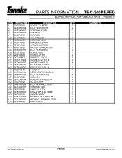
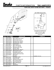
PARTS INFORMATION TBC-340PF,PFD CLUTCH, MUFFLER, ANTI-VIBE, FAN CASE • FIGURE 4 ITEM PART NUMBER DESCRIPTION 4-1 0160725020 COVER,CYLINDER 4-4 99463050164 BOLT,HEX,5X16,PS 4-5 99053060653 SCREW,HEX,6X65 4-6 99201060011 WASHER,6 4-7 7060725080 MUFFLER 4-10 7340725590 TAIL PIPE SET 4-11 99436040081 SCREW,4X18WS 4-13 7320725020 ARRESTER,SPARK 4-14 7510725020 GASKET,MUFFLER 4-21 7380725020 PROTECTOR,MUFFLER 4-24 99464040185 BOLT,HEX,4x18WS 4-30 2570725020 COVER,PLUG 4-35 2900138A80 SHOE,CLUTCH 4-36 3420138A20 SPRING,CLUTCH 4-37...
PARTS INFORMATION TBC-340PF,PFD CLUTCH, MUFFLER, ANTI-VIBE, FAN CASE • FIGURE 4 ITEM PART NUMBER DESCRIPTION 4-1 0160725020 COVER,CYLINDER 4-4 99463050164 BOLT,HEX,5X16,PS 4-5 99053060653 SCREW,HEX,6X65 4-6 99201060011 WASHER,6 4-7 7060725080 MUFFLER 4-10 7340725590 TAIL PIPE SET 4-11 99436040081 SCREW,4X18WS 4-13 7320725020 ARRESTER,SPARK 4-14 7510725020 GASKET,MUFFLER 4-21 7380725020 PROTECTOR,MUFFLER 4-24 99464040185 BOLT,HEX,4x18WS 4-30 2570725020 COVER,PLUG 4-35 2900138A80 SHOE,CLUTCH 4-36 3420138A20 SPRING,CLUTCH 4-37...
Parts List
Page 8
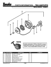
... are replacing the starter assy. PARTS INFORMATION TBC-340PF,PFD RECOIL STARTER • FIGURE 5 748732 Consider ordering the 748732, S-Start Kit if you are dependable and easy to install. ITEM PART NUMBER DESCRIPTION 5-0 7620162V900 STARTER,RECOIL ASS'Y 5-2 78501620200 HANDLE,STARTER 5-3 78006150200 GUIDE,ROPE 5-4 77206150200 BODY,RECOIL STARTER 5-5 7790136U200 SPRING,RECOIL 5-6 7830162V200 ROPE,STARTER,3.5X890 5-7 7740162V200 REEL,STARTER ROPE 5-8 8010162V200 WASHER,ROPE REEL 5-9 83900025200 SCREW,SET www.tanaka-usa.com Page 7 QTY 1 1 1 1 1 1 1 1 1 COMMENTS custsvc@tanaka...
... are replacing the starter assy. PARTS INFORMATION TBC-340PF,PFD RECOIL STARTER • FIGURE 5 748732 Consider ordering the 748732, S-Start Kit if you are dependable and easy to install. ITEM PART NUMBER DESCRIPTION 5-0 7620162V900 STARTER,RECOIL ASS'Y 5-2 78501620200 HANDLE,STARTER 5-3 78006150200 GUIDE,ROPE 5-4 77206150200 BODY,RECOIL STARTER 5-5 7790136U200 SPRING,RECOIL 5-6 7830162V200 ROPE,STARTER,3.5X890 5-7 7740162V200 REEL,STARTER ROPE 5-8 8010162V200 WASHER,ROPE REEL 5-9 83900025200 SCREW,SET www.tanaka-usa.com Page 7 QTY 1 1 1 1 1 1 1 1 1 COMMENTS custsvc@tanaka...

Parts List
Page 9
PARTS INFORMATION TBC-340PF,PFD CARBURETOR • FIGURE 6 ITEM PART NUMBER DESCRIPTION 6-0 4550304590 CARBURETOR SET 6-2 5752515380 BODY,PUMP 6-3 4422515180 PUMP,PRIMING 6-4 4762515120 COVER,DIAPHRAGM 6-5 44725108200 BULB,PRIMING 6-6 ~ ~ ~ METERING DIAPHRAGM 6-7 ~ ~ ~ DIAPHRAGM GASKET 6-8 ~ ~ ~ PUMP DIAPHRAGM 6-9 ~ ~ ~ PUMP GASKET 6-10 5992001W38 JET,MAIN LONG #38 6-11 55025100200 O-RING 6-12 48925100200 RING,STOP 6-13 53925120200 SWIVEL 6-15 51425100200 SCREW,THROTTLE SET 6-16 54425164200 STAY,ADJUST,CABLE 6-17 99101060003 NUT,6 6-18 61425137200 ADJUSTER,CABLE ...
PARTS INFORMATION TBC-340PF,PFD CARBURETOR • FIGURE 6 ITEM PART NUMBER DESCRIPTION 6-0 4550304590 CARBURETOR SET 6-2 5752515380 BODY,PUMP 6-3 4422515180 PUMP,PRIMING 6-4 4762515120 COVER,DIAPHRAGM 6-5 44725108200 BULB,PRIMING 6-6 ~ ~ ~ METERING DIAPHRAGM 6-7 ~ ~ ~ DIAPHRAGM GASKET 6-8 ~ ~ ~ PUMP DIAPHRAGM 6-9 ~ ~ ~ PUMP GASKET 6-10 5992001W38 JET,MAIN LONG #38 6-11 55025100200 O-RING 6-12 48925100200 RING,STOP 6-13 53925120200 SWIVEL 6-15 51425100200 SCREW,THROTTLE SET 6-16 54425164200 STAY,ADJUST,CABLE 6-17 99101060003 NUT,6 6-18 61425137200 ADJUSTER,CABLE ...
Parts List
Page 11
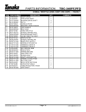
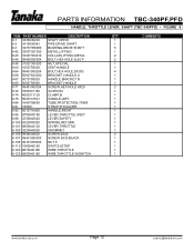
..., THROTTLE LEVER, SHAFT (TBC-340PF) • FIGURE 7 ITEM PART NUMBER DESCRIPTION 7-1 3433830220 SHAFT,DRIVE 7-2 3413830081 PIPE,DRIVE SHAFT 7-3 34737356900 BUSHING,DRIVE SHAFT 7-4 99101060041 NUT,6 7-5 5003738E20 HANDLE,FRONT 7-6 50633560200 BRACKET,HANDLE,BLACK 7-7 5033738E20 GRIP,HANDLE 7-8 99423060432 BOLT,6X43 7-9 8853739480 WIRE,THROTTLE 7-10 99311052012 SCREW,TAPPING 5X20 7-11 36832350200 WASHER,BRAKE SHAFT 7-25 8703738F90 LEVER,THROTTLE ASS'Y 7-26 1623710120 SWITCH,STOP 7-27 99342030081 SCREW,TAPPING,3X8 7-28 25937101200 BASE,STOP SWITCH 7-29 26237101200 SPRING...
..., THROTTLE LEVER, SHAFT (TBC-340PF) • FIGURE 7 ITEM PART NUMBER DESCRIPTION 7-1 3433830220 SHAFT,DRIVE 7-2 3413830081 PIPE,DRIVE SHAFT 7-3 34737356900 BUSHING,DRIVE SHAFT 7-4 99101060041 NUT,6 7-5 5003738E20 HANDLE,FRONT 7-6 50633560200 BRACKET,HANDLE,BLACK 7-7 5033738E20 GRIP,HANDLE 7-8 99423060432 BOLT,6X43 7-9 8853739480 WIRE,THROTTLE 7-10 99311052012 SCREW,TAPPING 5X20 7-11 36832350200 WASHER,BRAKE SHAFT 7-25 8703738F90 LEVER,THROTTLE ASS'Y 7-26 1623710120 SWITCH,STOP 7-27 99342030081 SCREW,TAPPING,3X8 7-28 25937101200 BASE,STOP SWITCH 7-29 26237101200 SPRING...
Parts List
Page 13
PARTS INFORMATION TBC-340PF,PFD HANDLE, THROTTLE LEVER, SHAFT (TBC-340PFD) • FIGURE 8 ITEM PART NUMBER DESCRIPTION 8-1 3433830220 SHAFT,DRIVE 8-2 3413830081 PIPE,DRIVE SHAFT 8-3 34737356900 BUSHING,DRIVE SHAFT 8-42 33537307200 METAL,LIFTING 8-43 33437352210 COLLAR,LIFTING METAL 8-44 99462050304 BOLT,HEX HOLE 5x30.P 8-46 31537304200 NUT,SPECIAL 8-63 1653759020 GRIP,HANDLE 8-64 99461050254 BOLT,HEX HOLE,5X25S 8-66 50637623200 BRACKET,HANDLE,A 8-67 5073785020 HANDLE BRACKET B 8-69 5083758920 BRACKET,HANDLE 8-71 99481060254 SCREW,HEX HOLE 6X25...
PARTS INFORMATION TBC-340PF,PFD HANDLE, THROTTLE LEVER, SHAFT (TBC-340PFD) • FIGURE 8 ITEM PART NUMBER DESCRIPTION 8-1 3433830220 SHAFT,DRIVE 8-2 3413830081 PIPE,DRIVE SHAFT 8-3 34737356900 BUSHING,DRIVE SHAFT 8-42 33537307200 METAL,LIFTING 8-43 33437352210 COLLAR,LIFTING METAL 8-44 99462050304 BOLT,HEX HOLE 5x30.P 8-46 31537304200 NUT,SPECIAL 8-63 1653759020 GRIP,HANDLE 8-64 99461050254 BOLT,HEX HOLE,5X25S 8-66 50637623200 BRACKET,HANDLE,A 8-67 5073785020 HANDLE BRACKET B 8-69 5083758920 BRACKET,HANDLE 8-71 99481060254 SCREW,HEX HOLE 6X25...
Parts List
Page 14
...,LINE 9-34 99317052002 SCREW,TAPPING,5x20 9-35 3013748000 SET,GEAR,PINION 9-37 44437609200 SPACER,BRACKET 9-38 99461050124 BOLT,HEX,5X12S 9-40 99101060011 NUT,6 9-41 99201060011 WASHER,6 www.tanaka-usa.com Page 13 This guard kit is NOT approved for use with 24 or 26 mm pipes. QTY COMMENTS 1 2 1 1 1 1 1 1 1 1 1 1 1 1 1 1 1 1 Available in kit only 1 1 1 1 2 2 2 2 custsvc@tanaka-ism.com This guard is designed to fit all trimmers...
...,LINE 9-34 99317052002 SCREW,TAPPING,5x20 9-35 3013748000 SET,GEAR,PINION 9-37 44437609200 SPACER,BRACKET 9-38 99461050124 BOLT,HEX,5X12S 9-40 99101060011 NUT,6 9-41 99201060011 WASHER,6 www.tanaka-usa.com Page 13 This guard kit is NOT approved for use with 24 or 26 mm pipes. QTY COMMENTS 1 2 1 1 1 1 1 1 1 1 1 1 1 1 1 1 1 1 Available in kit only 1 1 1 1 2 2 2 2 custsvc@tanaka-ism.com This guard is designed to fit all trimmers...
Parts List
Page 16
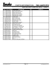
... CAP,CUTTER HOLDER 10-21 3083815020 COVER,BOLT PROTECTOR 10-22 3133815020 NUT,FIXING L.H. 10X1.25 10-23 3243815020 WASHER,GEAR CASE 10-26 99481060254 SCREW,HEX HOLE 6X25 10-28 4423369921 BRACKET 10-29 4413738020 GUARD,SAFETY 10-30 4453738020 HOLDER,GUARD 10-31 4473738020 EXTENSION,GUARD 10-32 7973738021 LIMITER,LINE 10-34 99414050121 SCREW,S,5X12 10-35 3013748000 SET,GEAR...
... CAP,CUTTER HOLDER 10-21 3083815020 COVER,BOLT PROTECTOR 10-22 3133815020 NUT,FIXING L.H. 10X1.25 10-23 3243815020 WASHER,GEAR CASE 10-26 99481060254 SCREW,HEX HOLE 6X25 10-28 4423369921 BRACKET 10-29 4413738020 GUARD,SAFETY 10-30 4453738020 HOLDER,GUARD 10-31 4473738020 EXTENSION,GUARD 10-32 7973738021 LIMITER,LINE 10-34 99414050121 SCREW,S,5X12 10-35 3013748000 SET,GEAR...
Parts List
Page 18
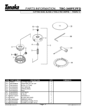
PARTS INFORMATION TBC-340PF,PFD CUTTING HEAD, BLADE & TOOLS (TBC-340PFD) • FIGURE 12 ITEM PART NUMBER DESCRIPTION 12-0 746451 CUTTING HEAD 12-2 3563383B20 ADAPTER,10x1.25 LHF 12-3 7863383020 BODY,CUTTING 12-4 3153383020 NUT,SPECIAL 12-5 7933383020 SPRING,REEL 12-6 7873383020 REEL 12-7 7893383020 CAP,BODY 12-8 7883383020 EYELET 12-10 99201120011 WASHER,12 12-29 746104 BLADE,SAW,9X80 12-30 81320000200 WRENCH,HEX,4 12-31 8262000080...
PARTS INFORMATION TBC-340PF,PFD CUTTING HEAD, BLADE & TOOLS (TBC-340PFD) • FIGURE 12 ITEM PART NUMBER DESCRIPTION 12-0 746451 CUTTING HEAD 12-2 3563383B20 ADAPTER,10x1.25 LHF 12-3 7863383020 BODY,CUTTING 12-4 3153383020 NUT,SPECIAL 12-5 7933383020 SPRING,REEL 12-6 7873383020 REEL 12-7 7893383020 CAP,BODY 12-8 7883383020 EYELET 12-10 99201120011 WASHER,12 12-29 746104 BLADE,SAW,9X80 12-30 81320000200 WRENCH,HEX,4 12-31 8262000080...
Parts List
Page 20
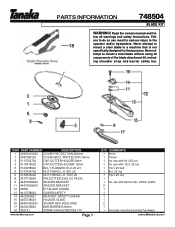
... operator and/or bystanders. Read the owners manual and fol- ing shoulder strap and barrier safety bar. PARTS INFORMATION 748504 BLADE KIT WARNING! Never at- low all components of the blade attachment kit, includ- ure to do so can result in serious injury to mount a steel blade without using all warnings and safety instructions. ITEM PART NUMBER DESCRIPTION 1 30833410200 COVER,PROTECTION,B,8mm 1 3083786120 COVER,BOLT PROTECTOR,10mm 3 3113754720 CAP...
... operator and/or bystanders. Read the owners manual and fol- ing shoulder strap and barrier safety bar. PARTS INFORMATION 748504 BLADE KIT WARNING! Never at- low all components of the blade attachment kit, includ- ure to do so can result in serious injury to mount a steel blade without using all warnings and safety instructions. ITEM PART NUMBER DESCRIPTION 1 30833410200 COVER,PROTECTION,B,8mm 1 3083786120 COVER,BOLT PROTECTOR,10mm 3 3113754720 CAP...

Handling Instructions
Page 7
... fully open. High speed mixture Use anti-slip and sturdy footwear. Meanings of thrown objects. Always wear eye, head and ear protectors when using your machine •Read the manual carefully. •Check that the cutting equipment is correctly assembled and adjusted. •Start the unit and check the carburetor adjustment. This reaction is what 2 Warnings and safety instructions 3 Specifications 4 Assembly procedures 5 Operating procedures 6 Maintenance 7 GB-1 Gloves...
... fully open. High speed mixture Use anti-slip and sturdy footwear. Meanings of thrown objects. Always wear eye, head and ear protectors when using your machine •Read the manual carefully. •Check that the cutting equipment is correctly assembled and adjusted. •Start the unit and check the carburetor adjustment. This reaction is what 2 Warnings and safety instructions 3 Specifications 4 Assembly procedures 5 Operating procedures 6 Maintenance 7 GB-1 Gloves...

Handling Instructions
Page 8
Drive shaft tube 7. Combi box spanner 18. Cutting attachment 6. Harness 11. Angle transmission 16. Joint case 17. Engine 15. Use the instructions that apply to your unit. Suspension eyelet 9. Throttle lock 12. Since this manual covers several models, there may be some difference between pictures and your unit. 1. Starter handle 4. Throttle trigger 3. Handle bar 8. Throttle trigger lookout 13. Handling instructions 10 10 10 GB-2 Ignition switch 10. What is what? Fuel cap 2. Blade guard 5. Choke lever 14.
Drive shaft tube 7. Combi box spanner 18. Cutting attachment 6. Harness 11. Angle transmission 16. Joint case 17. Engine 15. Use the instructions that apply to your unit. Suspension eyelet 9. Throttle lock 12. Since this manual covers several models, there may be some difference between pictures and your unit. 1. Starter handle 4. Throttle trigger 3. Handle bar 8. Throttle trigger lookout 13. Handling instructions 10 10 10 GB-2 Ignition switch 10. What is what? Fuel cap 2. Blade guard 5. Choke lever 14.

Handling Instructions
Page 9
...; Make sure engine switch is prolonged, take care and use common sense. Maintenance safety • Maintain the unit/machine according to recommended procedures. • Disconnect the spark plug before performing maintenance except for fuel leaks and make sure the cutting attachment has stopped before the unit is set down. • When operation is off engine. • Wear head protection. • Never start or run the engine inside...
...; Make sure engine switch is prolonged, take care and use common sense. Maintenance safety • Maintain the unit/machine according to recommended procedures. • Disconnect the spark plug before performing maintenance except for fuel leaks and make sure the cutting attachment has stopped before the unit is set down. • When operation is off engine. • Wear head protection. • Never start or run the engine inside...

Handling Instructions
Page 10
...) TBC-340 TBC-340D/340DS TBC-340PF TBC-340PFD/340PFDS 32.2 (1.96 cu.in ) CHAMPION RCJ6Y or equivalent 3,000 11,000 8,500 1.05 Fuel tank capacity (cm3) (ml) 700 (23.6 fl. Your risk from these chemicals are specially designed to change without notice. GB-4 speed (min-1) Speed of work with approved safety equipment, such as the time-weighted energy total for noise/vibration levels under...
...) TBC-340 TBC-340D/340DS TBC-340PF TBC-340PFD/340PFDS 32.2 (1.96 cu.in ) CHAMPION RCJ6Y or equivalent 3,000 11,000 8,500 1.05 Fuel tank capacity (cm3) (ml) 700 (23.6 fl. Your risk from these chemicals are specially designed to change without notice. GB-4 speed (min-1) Speed of work with approved safety equipment, such as the time-weighted energy total for noise/vibration levels under...

Handling Instructions
Page 11
... the gear case using Tanaka aluminum head (CH-100 or CH-300) on drive shaft tube against angle transmission. Install the blade guard to the guard bracket, which is hard to insert drive shaft up to carburetor (2). (Fig. 7) Cover throttle wire and stop cords (1). (Fig. 6) Connect throttle wire end (1) to air cleaner cover. (Fig. 8) Installation of the engine properly until the marked position (2) on the drive shaft tube meets the clutch case. Tighten the fixing bolt or nut with handling...
... the gear case using Tanaka aluminum head (CH-100 or CH-300) on drive shaft tube against angle transmission. Install the blade guard to the guard bracket, which is hard to insert drive shaft up to carburetor (2). (Fig. 7) Cover throttle wire and stop cords (1). (Fig. 6) Connect throttle wire end (1) to air cleaner cover. (Fig. 8) Installation of the engine properly until the marked position (2) on the drive shaft tube meets the clutch case. Tighten the fixing bolt or nut with handling...

Handling Instructions
Page 12
... thrust violently. Cutting (Fig. 22, 23, 24, 25) • When cutting, operate engine at least 15 m (50 ft.). Set choke lever to 5. 6. This is called BLADE THRUST. WARNING! Starting (Fig. 19, 20, 21) CAUTION! Make sure that fuel flows through the bulb or return pipe. (If so equipped) (Fig. 21) 2. For Tanaka BRAIN heads or Tanaka alloy head, use (JASO FC GRADE OIL or ISO EGC...
... thrust violently. Cutting (Fig. 22, 23, 24, 25) • When cutting, operate engine at least 15 m (50 ft.). Set choke lever to 5. 6. This is called BLADE THRUST. WARNING! Starting (Fig. 19, 20, 21) CAUTION! Make sure that fuel flows through the bulb or return pipe. (If so equipped) (Fig. 21) 2. For Tanaka BRAIN heads or Tanaka alloy head, use (JASO FC GRADE OIL or ISO EGC...

Handling Instructions
Page 13
... grass or vines wrap around attachment, stop engine and attachment and remove them. Carburetor adjustment (Fig. 27) WARNING! Otherwise the clutch can injure while it . When the engine is released. A further adjustment may be replaced with a new one adjustment possibility: T = Idle speed adjustment screw. If the cutting attachment still rotates after the engine is stopped or power control is test run at an idle for some time cannot be required, according to excessive dirt buildup, replace...
... grass or vines wrap around attachment, stop engine and attachment and remove them. Carburetor adjustment (Fig. 27) WARNING! Otherwise the clutch can injure while it . When the engine is released. A further adjustment may be replaced with a new one adjustment possibility: T = Idle speed adjustment screw. If the cutting attachment still rotates after the engine is stopped or power control is test run at an idle for some time cannot be required, according to excessive dirt buildup, replace...

Handling Instructions
Page 14
... impacts or cracks. • Check that the cutting attachment is undamaged. • Check the blade guard for damage or cracks. The spark plug should be replaced after about every 50 hours of operation by removing the grease filler plug on the blade. • Use a sharp blade. further information please contact Tanaka dealer. Weekly maintenance • Check the starter, especially cord. • Clean the exterior of angle transmission. Maintenance schedule Below you will fi...
... impacts or cracks. • Check that the cutting attachment is undamaged. • Check the blade guard for damage or cracks. The spark plug should be replaced after about every 50 hours of operation by removing the grease filler plug on the blade. • Use a sharp blade. further information please contact Tanaka dealer. Weekly maintenance • Check the starter, especially cord. • Clean the exterior of angle transmission. Maintenance schedule Below you will fi...

