Instruction Manual
Page 2
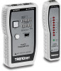
... to BNC can be added to carrying a tone that can be selected to expand the Network Cable Tester functionality. 1 The Network Cable Tester verifies continuity of shielded twisted pair (STP) cables. This tester is also included and individual pins/wires can be used for local loop-back test of a ... Scanning and Manual Scanning modes. The Network Cable Tester comes complete with BNC to RJ45 adapters for testing of pre-installed premise wiring. The Network Cable Tester comes in a convenient carrying pouch. The modular design enables the tester to be picked up with shielded connectors,...
... to BNC can be added to carrying a tone that can be selected to expand the Network Cable Tester functionality. 1 The Network Cable Tester verifies continuity of shielded twisted pair (STP) cables. This tester is also included and individual pins/wires can be used for local loop-back test of a ... Scanning and Manual Scanning modes. The Network Cable Tester comes complete with BNC to RJ45 adapters for testing of pre-installed premise wiring. The Network Cable Tester comes in a convenient carrying pouch. The modular design enables the tester to be picked up with shielded connectors,...
Instruction Manual
Page 3
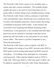
Tests pin to pin connection of the cable to be tested 2 DOING SO WHERE VOLTAGE IS PRESENT MAY DAMAGE THE TESTER. Auto - Checks for opens shorts and cross connected wires. 5. For loop-back and remote testing. 3. LOOP-BACK TEST 1. scan and manual step testing. 4. FEATURES: 1. Tests Lan, Telcom, UTP/STP and coax BNC cables. 6. To test patch cords, plug both ends of cables. 2. A. Tone feature easily locates remote cable ends. CAUTION: NOT FOR USE ON LIVE CIRCUITS.
Tests pin to pin connection of the cable to be tested 2 DOING SO WHERE VOLTAGE IS PRESENT MAY DAMAGE THE TESTER. Auto - Checks for opens shorts and cross connected wires. 5. For loop-back and remote testing. 3. LOOP-BACK TEST 1. scan and manual step testing. 4. FEATURES: 1. Tests Lan, Telcom, UTP/STP and coax BNC cables. 6. To test patch cords, plug both ends of cables. 2. A. Tone feature easily locates remote cable ends. CAUTION: NOT FOR USE ON LIVE CIRCUITS.

Instruction Manual
Page 4
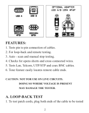
... press of LED will light (or not), in relation to the TX row, to indicate status. (b) Manual Scan Mode: By pressing the TEST button, the tester will advance the LED to the next one in sequence (1,2,..., shield and repeat), to -pin configuration (cross, 3 The RX row of the TEST button will... LED in the TX row will scroll in sequence (1,2,3,..., shield and repeat). (c) LED Status: When combining the information indicated by the RX and TX LEDs, a cable pin-to indicate the pins being tested.
... press of LED will light (or not), in relation to the TX row, to indicate status. (b) Manual Scan Mode: By pressing the TEST button, the tester will advance the LED to the next one in sequence (1,2,..., shield and repeat), to -pin configuration (cross, 3 The RX row of the TEST button will... LED in the TX row will scroll in sequence (1,2,3,..., shield and repeat). (c) LED Status: When combining the information indicated by the RX and TX LEDs, a cable pin-to indicate the pins being tested.
Instruction Manual
Page 6
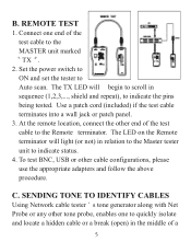
... Remote terminator will begin to scroll in the middle of the test cable to Auto scan. At the remote location, connect the other cable configurations, please use the appropriate adapters and follow the above procedure. SENDING TONE TO IDENTIFY CABLES Using Network cable tester s tone generator along with Net Probe or any other tone probe...
... Remote terminator will begin to scroll in the middle of the test cable to Auto scan. At the remote location, connect the other cable configurations, please use the appropriate adapters and follow the above procedure. SENDING TONE TO IDENTIFY CABLES Using Network cable tester s tone generator along with Net Probe or any other tone probe...
Instruction Manual
Page 7
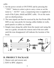
...button to select a pin to AUTO scan, a sequencing tone is supplied on shield position. 2. Or set the tester to carry a tone or set the main unit on each of the break. Simply trace along the cable from the master unit using the tone as a guide, towards the remote end of the test... cable until the tone disappeared will indicate the location of the 8 pins, shield and BNC cable. D. RJ45 to ON/TONE and by the Net Probe (PR06P) or any tone probe for tracing cables hidden in walls, patch panels or cables in a bundle. 3. cable 1. Set the power switch to ...
...button to select a pin to AUTO scan, a sequencing tone is supplied on shield position. 2. Or set the tester to carry a tone or set the main unit on each of the break. Simply trace along the cable from the master unit using the tone as a guide, towards the remote end of the test... cable until the tone disappeared will indicate the location of the 8 pins, shield and BNC cable. D. RJ45 to ON/TONE and by the Net Probe (PR06P) or any tone probe for tracing cables hidden in walls, patch panels or cables in a bundle. 3. cable 1. Set the power switch to ...
