TL-WA5210G V1 QIG 7106503701
Page 2
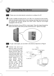
... location, select an elevated location where trees, buildings and large steel structures will not obstruct the antenna signals and which offers maximum line-of the Power Injector to a standard electrical wall socket. 2 2 Connecting the device Note Please use only wired network connections to the Antenna Alignment on Page 8. ..., and the other end of the Ethernet cable to the POE port of your CPE for your CPE. Finally, plug the provided power adapter into the DC jack on the back of the CPE. Locate a suitable mounting site for a best signal. Tighten the straps. Note To get a ...
... location, select an elevated location where trees, buildings and large steel structures will not obstruct the antenna signals and which offers maximum line-of the Power Injector to a standard electrical wall socket. 2 2 Connecting the device Note Please use only wired network connections to the Antenna Alignment on Page 8. ..., and the other end of the Ethernet cable to the POE port of your CPE for your CPE. Finally, plug the provided power adapter into the DC jack on the back of the CPE. Locate a suitable mounting site for a best signal. Tighten the straps. Note To get a ...
TL-WA5210G V1 QIG 7106503701
Page 3
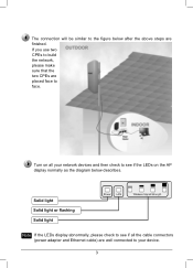
Solid light Solid light or flashing Solid light Note If the LEDs display abnormally, please check to see if all the cable connectors (power adapter and Ethernet cable) are well connected to your network devices and then check to see if the LEDs on all your device. 3 Turn on the AP display normally as the diagram below after the above steps are placed face to face. The connection will be similar to the figure below describes. If you use two CPEs to build the network, please make sure that the two CPEs are finished.
Solid light Solid light or flashing Solid light Note If the LEDs display abnormally, please check to see if all the cable connectors (power adapter and Ethernet cable) are well connected to your network devices and then check to see if the LEDs on all your device. 3 Turn on the AP display normally as the diagram below after the above steps are placed face to face. The connection will be similar to the figure below describes. If you use two CPEs to build the network, please make sure that the two CPEs are finished.


