

TL-SL2210 V1 IG 7106504458
Page 3
...Website: http://www.tp-link.com About this Installation Guide This Installation Guide describes the hardware characteristics, installation methods and the points that should be attended to the Switch. This chapter describes the External Components of the switch. Chapter 2 Installation...Protection. This chapter illustrates how to install the switch. Appendix B Hardware Specifications. This chapter illustrates how to the switch via Web Interface. This chapter illustrates how to do the physical connection of the Switch. Appendix C Technical Support. Chapter 4 Connection....
...Website: http://www.tp-link.com About this Installation Guide This Installation Guide describes the hardware characteristics, installation methods and the points that should be attended to the Switch. This chapter describes the External Components of the switch. Chapter 2 Installation...Protection. This chapter illustrates how to install the switch. Appendix B Hardware Specifications. This chapter illustrates how to the switch via Web Interface. This chapter illustrates how to do the physical connection of the Switch. Appendix C Technical Support. Chapter 4 Connection....
TL-SL2210 V1 IG 7106504458
Page 4
Audience This Installation Guide is for a better use of TL-SL2210/TL-SL2218/TL-SL2428/TL-SL2452 Smart Switch, in this guide. The following table lists the notice icons that are used throughout this Installation Guide we take notice. Remind to highlight special messages. Remind to take TL-SL2218 as an example to illustrate Chapter 2 Installation, Chapter 3 Lightning...
Audience This Installation Guide is for a better use of TL-SL2210/TL-SL2218/TL-SL2428/TL-SL2452 Smart Switch, in this guide. The following table lists the notice icons that are used throughout this Installation Guide we take notice. Remind to highlight special messages. Remind to take TL-SL2218 as an example to illustrate Chapter 2 Installation, Chapter 3 Lightning...

TL-SL2210 V1 IG 7106504458
Page 5
... Use Lightning Arrester 14 Chapter 4 4.1 4.2 4.3 4.4 4.5 Connection 16 Ethernet Port 16 SFP Port 16 Verify Installation 17 Power On 17 Initialization 17 Chapter 5 Login to the Switch 18 Appendix A Troubleshooting 19 Appendix B Hardware Specifications- -------- 20 Appendix C Technical Support 21 Contents IV
... Use Lightning Arrester 14 Chapter 4 4.1 4.2 4.3 4.4 4.5 Connection 16 Ethernet Port 16 SFP Port 16 Verify Installation 17 Power On 17 Initialization 17 Chapter 5 Login to the Switch 18 Appendix A Troubleshooting 19 Appendix B Hardware Specifications- -------- 20 Appendix C Technical Support 21 Contents IV

TL-SL2210 V1 IG 7106504458
Page 6
... interface, via which can fully meet the need of the users demanding higher networking performance. 1111 Appearance ■■ Front Panel The front panel of TL-SL2210 is compliant with high security. Smart Switch CCCCCCCCCC Introduction 1111 Product Overview TL-SL2210/TL-SL2218/TL-SL2428/TL-SL2452 is shown as Figure 1-1.
... interface, via which can fully meet the need of the users demanding higher networking performance. 1111 Appearance ■■ Front Panel The front panel of TL-SL2210 is compliant with high security. Smart Switch CCCCCCCCCC Introduction 1111 Product Overview TL-SL2210/TL-SL2218/TL-SL2428/TL-SL2452 is shown as Figure 1-1.
TL-SL2210 V1 IG 7106504458
Page 7
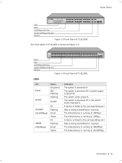
... FFFFFFFFFFFFront Panel of TL-SL2428 The front panel of TL-SL2452 LEDs LED Power System Status On(green1 Off/ Flashing Flashing On/Off 10/100M (10/100Mbps1 1000M (1000Mbps1 On Flashing Green Yellow On Flashing Green Yellow Indication The switch is powered on The switch is powered off ...or power supply is abnormal The switch works properly The switch is powered off or the switch works improperly A device is linked to the corresponding port Data is being transmitted or received...
... FFFFFFFFFFFFront Panel of TL-SL2428 The front panel of TL-SL2452 LEDs LED Power System Status On(green1 Off/ Flashing Flashing On/Off 10/100M (10/100Mbps1 1000M (1000Mbps1 On Flashing Green Yellow On Flashing Green Yellow Indication The switch is powered on The switch is powered off ...or power supply is abnormal The switch works properly The switch is powered off or the switch works improperly A device is linked to the corresponding port Data is being transmitted or received...
TL-SL2210 V1 IG 7106504458
Page 8
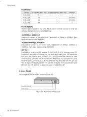
... Panel of 10Mbps or 100Mbps. Smart Switch Port Feature Model TL-SL2210 TL-SL2218 TL-SL2428 TL-SL2452 10/100Mbps RJ45 Port 8 16 24 48 10/100/1000Mbps RJ45 Port 1 2 4 2 SFP Port 1 2(Combo1 2(Combo1 2 Reset(RESET) With the switch powered on, press Reset button for TL-SL2428 Port 27 shares the same LED... with Port 27F and Port 28 shares the same LED with Port 28F. ■■ Rear Panel The rear panel of TL-SL2210 is shown as a "Combo" port, which means...
... Panel of 10Mbps or 100Mbps. Smart Switch Port Feature Model TL-SL2210 TL-SL2218 TL-SL2428 TL-SL2452 10/100Mbps RJ45 Port 8 16 24 48 10/100/1000Mbps RJ45 Port 1 2 4 2 SFP Port 1 2(Combo1 2(Combo1 2 Reset(RESET) With the switch powered on, press Reset button for TL-SL2428 Port 27 shares the same LED... with Port 27F and Port 28 shares the same LED with Port 28F. ■■ Rear Panel The rear panel of TL-SL2210 is shown as a "Combo" port, which means...
TL-SL2210 V1 IG 7106504458
Page 9
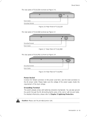
... male connector to Chapter 3 Lightning Protection. Smart Switch Power Socket Grounding Terminal FFFFFFFFFFFFRear Panel of TL-SL2218 The rear panel of TL-SL2452 is shown as Figure 1-6. Grounding Terminal Power Socket FFFFFFFFFFFFRear Panel of TL-SL2428 The rear panel of TL-SL2428 is shown as Figure 1-8. Grounding Terminal The switch already comes with Ground Cable. Introduction 04...
... male connector to Chapter 3 Lightning Protection. Smart Switch Power Socket Grounding Terminal FFFFFFFFFFFFRear Panel of TL-SL2218 The rear panel of TL-SL2452 is shown as Figure 1-6. Grounding Terminal Power Socket FFFFFFFFFFFFRear Panel of TL-SL2428 The rear panel of TL-SL2428 is shown as Figure 1-8. Grounding Terminal The switch already comes with Ground Cable. Introduction 04...
TL-SL2210 V1 IG 7106504458
Page 10
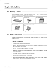
... , please observe the following items. If any other liquid cleaning method. 05 Installation Do not clean it by improper use any of the switch. ■■ Before cleaning the device, cut off during the installation. ■■ Wear an ESD-preventive wrist strap, and make .... ■■ Do not open or remove the cover of the listed items is damaged or missing, please contact your distributor. Smart Switch CCCCCCCCCC Installation 2222 Package Contents Make sure that the package contains the following rules. ■■ Safety Precautions ■■ Keep the ...
... , please observe the following items. If any other liquid cleaning method. 05 Installation Do not clean it by improper use any of the switch. ■■ Before cleaning the device, cut off during the installation. ■■ Wear an ESD-preventive wrist strap, and make .... ■■ Do not open or remove the cover of the listed items is damaged or missing, please contact your distributor. Smart Switch CCCCCCCCCC Installation 2222 Package Contents Make sure that the package contains the following rules. ■■ Safety Precautions ■■ Keep the ...
TL-SL2210 V1 IG 7106504458
Page 11
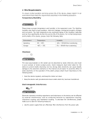
...cause deadly damage to bad insulation, electricity leakage, mechanical property changes and corrosions. To avoid the effect of static electricity on the switch can be affected by external interferences, such as conducted emission by static electricity and result in the equipment room. Too high/low...557; Please keep the indoor air clean. ■■ Keep the device well grounded and ensure static electricity has been transferred. Smart Switch ■■ Site Requirements To ensure normal operation and long service life of the device, please install it in an environment that can...
...cause deadly damage to bad insulation, electricity leakage, mechanical property changes and corrosions. To avoid the effect of static electricity on the switch can be affected by external interferences, such as conducted emission by static electricity and result in the equipment room. Too high/low...557; Please keep the indoor air clean. ■■ Keep the device well grounded and ensure static electricity has been transferred. Smart Switch ■■ Site Requirements To ensure normal operation and long service life of the device, please install it in an environment that can...
TL-SL2210 V1 IG 7106504458
Page 12
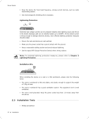
... this instant current is strong enough to damage electronic devices, more effective lightning protection measures should be instantly heated up to 20,000℃. Smart Switch ■■ Keep the device far from the device. 2222 Installation Tools ■■ Phillips screwdriver 07 Installation Note: For detailed lightning protection measures, please...
... this instant current is strong enough to damage electronic devices, more effective lightning protection measures should be instantly heated up to 20,000℃. Smart Switch ■■ Keep the device far from the device. 2222 Installation Tools ■■ Phillips screwdriver 07 Installation Note: For detailed lightning protection measures, please...
TL-SL2210 V1 IG 7106504458
Page 13
Smart Switch ■■ ESD-preventive wrist wrap ■■ Cables Note: These tools are not provided with supplied screws, as illustrated in an EIA standard-sized, ...
Smart Switch ■■ ESD-preventive wrist wrap ■■ Cables Note: These tools are not provided with supplied screws, as illustrated in an EIA standard-sized, ...
TL-SL2210 V1 IG 7106504458
Page 14
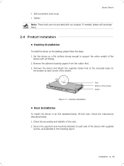
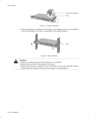
Rack FFFFFFFFFFF Rack Installation Caution: ■■ Please set 5~10cm gaps around the device for the purpose of heat dissipation. 09 Installation Smart Switch Rackmounting Bracket Screw FFFFFFFFFFF Bracket Installation 333After the brackets are attached to the device, use suitable screws (not provided) to secure the brackets to the ...
Rack FFFFFFFFFFF Rack Installation Caution: ■■ Please set 5~10cm gaps around the device for the purpose of heat dissipation. 09 Installation Smart Switch Rackmounting Bracket Screw FFFFFFFFFFF Bracket Installation 333After the brackets are attached to the device, use suitable screws (not provided) to secure the brackets to the ...
TL-SL2210 V1 IG 7106504458
Page 15
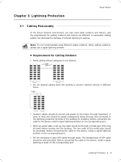
... Protection 10 The shielded layer of this metal pipe should be well grounded. Note: It's not recommended using Ethernet cables outdoors. CCCCCCCCCC Lightning Protection Smart Switch 3333 Cabling Reasonably In the actual network environment, you may need cable outdoors and indoors, and the requirements for Cabling Outdoors ■■ Aerial cabling...
... Protection 10 The shielded layer of this metal pipe should be well grounded. Note: It's not recommended using Ethernet cables outdoors. CCCCCCCCCC Lightning Protection Smart Switch 3333 Cabling Reasonably In the actual network environment, you may need cable outdoors and indoors, and the requirements for Cabling Outdoors ■■ Aerial cabling...
TL-SL2210 V1 IG 7106504458
Page 16
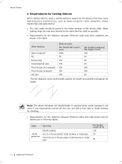
... H (mm1 300 20 20 20 500 300 20 The two diagrams below demonstrate parallel net length and parallel-overlapping net height. Cable Pave Way Smart Switch ■■ Requirements for Cabling Indoors When cabling indoors, keep the loop area formed by the cable itself as small as down-conductor cable, powerline...
... H (mm1 300 20 20 20 500 300 20 The two diagrams below demonstrate parallel net length and parallel-overlapping net height. Cable Pave Way Smart Switch ■■ Requirements for Cabling Indoors When cabling indoors, keep the loop area formed by the cable itself as small as down-conductor cable, powerline...

TL-SL2210 V1 IG 7106504458
Page 17
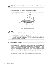
... connect the device to the ground in two ways, connecting to the grounding bar or connecting to protect the body from electric shock. Switch (Rear Panel) Ground Cable Grounding Terminal Grounding Bar FFFFFFFFFFF Connecting to the grounding bar as shown in the following will instruct you are ...in the grounded metal raceway or metal pipe 150 Device Switch case Transformer room Elevator tower Air-conditioner room Min Distance (m1 1.00 2.00 2.00 2.00 3333 Connect to Ground Connecting the device...
... connect the device to the ground in two ways, connecting to the grounding bar or connecting to protect the body from electric shock. Switch (Rear Panel) Ground Cable Grounding Terminal Grounding Bar FFFFFFFFFFF Connecting to the grounding bar as shown in the following will instruct you are ...in the grounded metal raceway or metal pipe 150 Device Switch case Transformer room Elevator tower Air-conditioner room Min Distance (m1 1.00 2.00 2.00 2.00 3333 Connect to Ground Connecting the device...
TL-SL2210 V1 IG 7106504458
Page 18
... as shown in a network. 13 Lightning Protection FFFFFFFFFFF Connecting to the Ground Note: ■■ The figure is to illustrate the application and principle. Smart Switch Note: The grounding bar and the ground cable are not provided with the regulation in your country, so they may differ from the figure above...
... as shown in a network. 13 Lightning Protection FFFFFFFFFFF Connecting to the Ground Note: ■■ The figure is to illustrate the application and principle. Smart Switch Note: The grounding bar and the ground cable are not provided with the regulation in your country, so they may differ from the figure above...
TL-SL2210 V1 IG 7106504458
Page 19
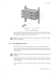
... our product. Note: Power lightning arrester is used for limiting the voltage surge due to the device, please use a grounding bar to the device. Smart Switch Grounding Terminal Ground Cable Equipotential Bonding Cable Grounding Bar FFFFFFFFFFF Equipotential Bonding When equipotential bonding, please note that the cable should be copper wrapped Kelly...
... our product. Note: Power lightning arrester is used for limiting the voltage surge due to the device, please use a grounding bar to the device. Smart Switch Grounding Terminal Ground Cable Equipotential Bonding Cable Grounding Bar FFFFFFFFFFF Equipotential Bonding When equipotential bonding, please note that the cable should be copper wrapped Kelly...
TL-SL2210 V1 IG 7106504458
Page 20
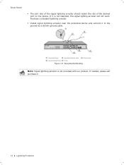
.... ■■ Install signal lightning arrester near the protected device and connect it . 15 Lightning Protection If it is not provided with our product. Smart Switch ■■ The port rate of the signal lightning arrester should match the rate of the desired port on the device.
.... ■■ Install signal lightning arrester near the protected device and connect it . 15 Lightning Protection If it is not provided with our product. Smart Switch ■■ The port rate of the signal lightning arrester should match the rate of the desired port on the device.

TL-SL2210 V1 IG 7106504458
Page 21
... Module FFFFFFFFFFF Connecting the LAN Port Note: ■■ SFP module supports hot-plugging, plug the SFP module into the SFP port and the switch can only be used with a gigabit module. For 100M module, please select 100MFD while select 1000MFD for gigabit module. When using a SFP module...Ethernet Port Please connect the Ethernet ports of the switch to the GUI of SFP mode is installed in a slot and has a valid link on the port, the associated RJ45 port will be disabled and cannot be used . Connection 16 For TL-SL2210/TL-SL2452, the SFP port can identify it automatically. &#...
... Module FFFFFFFFFFF Connecting the LAN Port Note: ■■ SFP module supports hot-plugging, plug the SFP module into the SFP port and the switch can only be used with a gigabit module. For 100M module, please select 100MFD while select 1000MFD for gigabit module. When using a SFP module...Ethernet Port Please connect the Ethernet ports of the switch to the GUI of SFP mode is installed in a slot and has a valid link on the port, the associated RJ45 port will be disabled and cannot be used . Connection 16 For TL-SL2210/TL-SL2452, the SFP port can identify it automatically. &#...
TL-SL2210 V1 IG 7106504458
Page 22
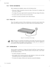
... after initialization. ■■ The System LED indicator will comply with the regulation in your situation will flash, which represents a successful initialization. 17 Connection Smart Switch 4444 Verify Installation After completing the installation, please verify the following figure shown.
... after initialization. ■■ The System LED indicator will comply with the regulation in your situation will flash, which represents a successful initialization. 17 Connection Smart Switch 4444 Verify Installation After completing the installation, please verify the following figure shown.

