
TL-SG3424P V1 User Guide
Page 3
... this Guide...2 1.1 Intended Readers ...2 1.2 Conventions...2 1.3 Overview of This Guide 2 Chapter 2 Introduction ...6 2.1 Overview of the Switch 6 2.2 Main Features...6 2.3 Appearance Description 7 2.3.1 Front Panel ...7 2.3.2 Rear Panel ...9 Chapter 3 Login to the Switch...10 3.1 Login...10 3.2 Configuration ...10 Chapter 4 System ...12 4.1 System Info...12 4.1.1 System Summary 12 4.1.2 Device Description... 4.3.5 System Reset 21 4.4 Access Security ...21 4.4.1 Access Control 21 4.4.2 SSL Config...23 4.4.3 SSH Config ...24 Chapter 5 Switching...30 5.1 Port ...30 5.1.1 Port Config ...30 IV
... this Guide...2 1.1 Intended Readers ...2 1.2 Conventions...2 1.3 Overview of This Guide 2 Chapter 2 Introduction ...6 2.1 Overview of the Switch 6 2.2 Main Features...6 2.3 Appearance Description 7 2.3.1 Front Panel ...7 2.3.2 Rear Panel ...9 Chapter 3 Login to the Switch...10 3.1 Login...10 3.2 Configuration ...10 Chapter 4 System ...12 4.1 System Info...12 4.1.1 System Summary 12 4.1.2 Device Description... 4.3.5 System Reset 21 4.4 Access Security ...21 4.4.1 Access Control 21 4.4.2 SSL Config...23 4.4.3 SSH Config ...24 Chapter 5 Switching...30 5.1 Port ...30 5.1.1 Port Config ...30 IV

TL-SG3424P V1 User Guide
Page 9
Package Contents The following items should be found in your box: ¾ One JetStream L2 Managed PoE Switch ¾ One power cord ¾ One console cable ¾ Two mounting brackets and other fittings ¾ Installation Guide ¾ Resource CD for TL-SG3424P switch, including: • This User Guide • Other Helpful Information Note: Make sure that the package contains the above items. If any of the listed items are damaged or missing, please contact your distributor. 1
Package Contents The following items should be found in your box: ¾ One JetStream L2 Managed PoE Switch ¾ One power cord ¾ One console cable ¾ Two mounting brackets and other fittings ¾ Installation Guide ¾ Resource CD for TL-SG3424P switch, including: • This User Guide • Other Helpful Information Note: Make sure that the package contains the above items. If any of the listed items are damaged or missing, please contact your distributor. 1
TL-SG3424P V1 User Guide
Page 10
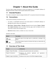
... managers familiar with IT concepts and network terminologies. 1.2 Conventions In this Guide the following conventions are used: ¾ The switch or TL-SG3424P mentioned in this Guide stands for setup and management of note might result in a malfunction or damage to the device. Introduces... Intended Readers This Guide is located under the System Info menu option that helps you make better use of your device. 1.3 Overview of TL-SG3424P switch. System→System Info→System Summary means the System Summary page under the System menu. ¾ Bold font indicates a button,...
... managers familiar with IT concepts and network terminologies. 1.2 Conventions In this Guide the following conventions are used: ¾ The switch or TL-SG3424P mentioned in this Guide stands for setup and management of note might result in a malfunction or damage to the device. Introduces... Intended Readers This Guide is located under the System Info menu option that helps you make better use of your device. 1.3 Overview of TL-SG3424P switch. System→System Info→System Summary means the System Summary page under the System menu. ¾ Bold font indicates a button,...

TL-SG3424P V1 User Guide
Page 11
...multicast data traffic on to the Web management page with a certain access level. This module is used to configure multicast function of the switch. z LAG: Configure Link Aggregation Group. z Protocol VLAN: Create VLANs in the specified VLAN. Here mainly introduces: z STP Config: Configure and view the global...each port of each VLAN. Here mainly introduces: z System Info: Configure the description, system time and network parameters of the switch. This module is used to configure VLANs to control broadcast in the network. 3 This module is used to configure basic functions of ...
...multicast data traffic on to the Web management page with a certain access level. This module is used to configure multicast function of the switch. z LAG: Configure Link Aggregation Group. z Protocol VLAN: Create VLANs in the specified VLAN. Here mainly introduces: z STP Config: Configure and view the global...each port of each VLAN. Here mainly introduces: z System Info: Configure the description, system time and network parameters of the switch. This module is used to configure VLANs to control broadcast in the network. 3 This module is used to configure basic functions of ...

TL-SG3424P V1 User Guide
Page 12
... time for PoE port to supply power.. z Notification: Configure notification function for PD devices. This module is used to configure the PoE function for the switch to supply power for the management station to monitor network more efficiently. 4 Here mainly introduces: z PoE Config: Configure PoE function globally.
... time for PoE port to supply power.. z Notification: Configure notification function for PD devices. This module is used to configure the PoE function for the switch to supply power for the management station to monitor network more efficiently. 4 Here mainly introduces: z PoE Config: Configure PoE function globally.

TL-SG3424P V1 User Guide
Page 13
...NDP function to get the information of the device. z Cluster: Configure cluster function to CONTENTS 5 z Log: View configuration parameters on the switch. Return to establish and maintain cluster. Introduces how to the destination. z Device Info: View the LLDP information of the local device and its...System Maintenance via FTP Appendix D 802.1X Client Software Appendix E Glossary Introduction This module is used system tools to manage the switch. Lists the hardware specifications of the device. This module is used in the network. Introduces how to use 802.1X Client ...
...NDP function to get the information of the device. z Cluster: Configure cluster function to CONTENTS 5 z Log: View configuration parameters on the switch. Return to establish and maintain cluster. Introduces how to the destination. z Device Info: View the LLDP information of the local device and its...System Maintenance via FTP Appendix D 802.1X Client Software Appendix E Glossary Introduction This module is used system tools to manage the switch. Lists the hardware specifications of the device. This module is used in the network. Introduces how to use 802.1X Client ...

TL-SG3424P V1 User Guide
Page 14
...such as 802.1x, RADIUS. + Dynamic ARP Inspection blocks ARP packets from TP-LINK provides wire-speed performance and abundant layer 2 management features. TL-SG3424P Managed PoE Switch is friendly to manage, which can provide flexible solutions for access encryption. •... Manageability + IP Clustering provides high scalability and easy Single-IP-Management. 6 TL-SG3424P Switch integrates multiple functions with excellent performance, and is also a Power Sourcing Equipment. Link aggregation (LACP) increases aggregated bandwidth, optimizing the transport of business critical data...
...such as 802.1x, RADIUS. + Dynamic ARP Inspection blocks ARP packets from TP-LINK provides wire-speed performance and abundant layer 2 management features. TL-SG3424P Managed PoE Switch is friendly to manage, which can provide flexible solutions for access encryption. •... Manageability + IP Clustering provides high scalability and easy Single-IP-Management. 6 TL-SG3424P Switch integrates multiple functions with excellent performance, and is also a Power Sourcing Equipment. Link aggregation (LACP) increases aggregated bandwidth, optimizing the transport of business critical data...

TL-SG3424P V1 User Guide
Page 15
...to connect with the serial port of a computer or terminal for monitoring and configuring the Switch. ¾ LEDs TL-SG3424P has a LED mode switch button which is indicating the data transmission rate. Pressing the mode switch button, the Speed LED will turn off and the PoE LED will turn off or power... supply is abnormal. LED Status Indication On The Switch is powered on , the port LED ...
...to connect with the serial port of a computer or terminal for monitoring and configuring the Switch. ¾ LEDs TL-SG3424P has a LED mode switch button which is indicating the data transmission rate. Pressing the mode switch button, the Speed LED will turn off and the PoE LED will turn off or power... supply is abnormal. LED Status Indication On The Switch is powered on , the port LED ...

TL-SG3424P V1 User Guide
Page 16
... supply status. Data is being transmitted or received A 10/100 Mbps device is on for 2 minutes. LED Status Indication On The Switch is provided on . The Switch works improperly. Off No PoE power supply is powered on the port. 8 Port LED Flashing Power-on , the port LED is abnormal... 1000 Mbps device is connected to the corresponding port When the PoE LED is on self-test has failed. System Flashing On/Off The Switch works properly. PoE Max Flashing The remaining PoE power keeps ≤7W after this LED is connected to the corresponding port, but no ...
... supply status. Data is being transmitted or received A 10/100 Mbps device is on for 2 minutes. LED Status Indication On The Switch is provided on . The Switch works improperly. Off No PoE power supply is powered on the port. 8 Port LED Flashing Power-on , the port LED is abnormal... 1000 Mbps device is connected to the corresponding port When the PoE LED is on self-test has failed. System Flashing On/Off The Switch works properly. PoE Max Flashing The remaining PoE power keeps ≤7W after this LED is connected to the corresponding port, but no ...

TL-SG3424P V1 User Guide
Page 17
...rear panel of the input voltage (100-240V~ 50/60Hz 0.6A). Please make sure the voltage of the power supply meets the requirement of TL-SG3424P features a power socket and a Grounding Terminal (marked with ). Return to Installation Guide. ¾ AC Power Socket: Connect the female connector ...of AC cord or with Lightning Protection Mechanism. Figure 2-2 Rear Panel ¾ Grounding Terminal: TL-SG3424P already comes with Ground Cable. You can also ground the Switch through the PE (Protecting Earth) cable of the power cord here, and the male connector to the AC...
...rear panel of the input voltage (100-240V~ 50/60Hz 0.6A). Please make sure the voltage of the power supply meets the requirement of TL-SG3424P features a power socket and a Grounding Terminal (marked with ). Return to Installation Guide. ¾ AC Power Socket: Connect the female connector ...of AC cord or with Lightning Protection Mechanism. Figure 2-2 Rear Panel ¾ Grounding Terminal: TL-SG3424P already comes with Ground Cable. You can also ground the Switch through the PE (Protecting Earth) cable of the power cord here, and the male connector to the AC...

TL-SG3424P V1 User Guide
Page 18
Enter admin for the User Name and Password, both in the address field of the Switch. Chapter 3 Login to the Switch 3.1 Login 1) To access the configuration utility, open a web-browser and type in the default address http://192.168.0.1 in lower case letters. The IP address ...is 192.168.0.x ("x" is any number from 2 to the Switch, the IP address of the screen. 10 For the detailed instructions as to how to do this, please refer to Appendix B. 2) After a moment, a login window...
Enter admin for the User Name and Password, both in the address field of the Switch. Chapter 3 Login to the Switch 3.1 Login 1) To access the configuration utility, open a web-browser and type in the default address http://192.168.0.1 in lower case letters. The IP address ...is 192.168.0.x ("x" is any number from 2 to the Switch, the IP address of the screen. 10 For the detailed instructions as to how to do this, please refer to Appendix B. 2) After a moment, a login window...

TL-SG3424P V1 User Guide
Page 19
You are suggested to click Saving Config before the switch is rebooted, please click Saving Config. Return to keep the configurations effective even the switch is rebooted. Figure 3-3 Main Setup-Menu Note: Clicking Apply can only make the new configurations effective before cutting off the power or rebooting the switch to avoid losing the new configurations. If you want to CONTENTS 11
You are suggested to click Saving Config before the switch is rebooted, please click Saving Config. Return to keep the configurations effective even the switch is rebooted. Figure 3-3 Main Setup-Menu Note: Clicking Apply can only make the new configurations effective before cutting off the power or rebooting the switch to avoid losing the new configurations. If you want to CONTENTS 11

TL-SG3424P V1 User Guide
Page 20
Indicates the 1000Mbps port is at the speed of the switch, including four submenus: System Info, User Manage, System Tools and Access Security. 4.1 System Info The System Info, mainly for system configuration of 1000Mbps. The ports ... of 24 10/100/1000Mbps RJ45 ports and 4 SFP ports of 10Mbps or 100Mbps. 12 Indicates the 1000Mbps port is at the speed of the switch. Choose the menu System→System Info→System Summary to load the following page. ¾ Port Status Figure 4-1 System Summary Indicates the 1000Mbps port...
Indicates the 1000Mbps port is at the speed of the switch, including four submenus: System Info, User Manage, System Tools and Access Security. 4.1 System Info The System Info, mainly for system configuration of 1000Mbps. The ports ... of 24 10/100/1000Mbps RJ45 ports and 4 SFP ports of 10Mbps or 100Mbps. 12 Indicates the 1000Mbps port is at the speed of the switch. Choose the menu System→System Info→System Summary to load the following page. ¾ Port Status Figure 4-1 System Summary Indicates the 1000Mbps port...

TL-SG3424P V1 User Guide
Page 21
..., the detailed information of the port will be displayed. ¾ Port Info Figure 4-2 Port Information Port: Type: Rate: Status: Displays the port number of the switch. Indicates the SFP port is not connected to a device. Indicates the SFP port is at the speed of 1000Mbps.
..., the detailed information of the port will be displayed. ¾ Port Info Figure 4-2 Port Information Port: Type: Rate: Status: Displays the port number of the switch. Indicates the SFP port is not connected to a device. Indicates the SFP port is at the speed of 1000Mbps.

TL-SG3424P V1 User Guide
Page 22
.... Figure 4-4 Device Description The following entries are displayed on this port. 4.1.2 Device Description On this page you can configure the description of the switch, including device name, device location and system contact. Tx: Select Tx to display the bandwidth utilization of sending packets on this port. Rx: ...bandwidth utilization of receiving packets on this screen: ¾ Device Description Device Name: Device Location: System Contact: Enter the name of the switch. Enter your contact information. 4.1.3 System Time System Time is the time displayed while the...
.... Figure 4-4 Device Description The following entries are displayed on this port. 4.1.2 Device Description On this page you can configure the description of the switch, including device name, device location and system contact. Tx: Select Tx to display the bandwidth utilization of sending packets on this port. Rx: ...bandwidth utilization of receiving packets on this screen: ¾ Device Description Device Name: Device Location: System Contact: Enter the name of the switch. Enter your contact information. 4.1.3 System Time System Time is the time displayed while the...

TL-SG3424P V1 User Guide
Page 23
... administrator PC's clock is selected, you can configure the time zone and the IP Address for the NTP Server. Select the Start Time of the switch. ¾ Time Config Manual: Get GMT: Synchronize with PC'S Clock: When this option is utilized. ¾ DST Config DST Status: Start Time: End Time: Enable... or Disable DST. When this option is selected, you can set the date and time manually. The switch will get GMT automatically if it has connected to a NTP Server. Current Time Source: Displays the current time source of DST.
... administrator PC's clock is selected, you can configure the time zone and the IP Address for the NTP Server. Select the Start Time of the switch. ¾ Time Config Manual: Get GMT: Synchronize with PC'S Clock: When this option is utilized. ¾ DST Config DST Status: Start Time: End Time: Enable... or Disable DST. When this option is selected, you can set the date and time manually. The switch will get GMT automatically if it has connected to a NTP Server. Current Time Source: Displays the current time source of DST.

TL-SG3424P V1 User Guide
Page 24
...got time successfully or from the public time server in its default network. 4.1.4 System IP Each device in the network possesses a unique IP Address. The switch supports three modes to a port that is a member of management VLAN, the only VLAN through which you can log on this option is selected, ...you can get access to the switch. Enter the ID of the Management VLAN. IP Address Mode: Management VLAN: Select the mode to load the following entries are displayed on to ...
...got time successfully or from the public time server in its default network. 4.1.4 System IP Each device in the network possesses a unique IP Address. The switch supports three modes to a port that is a member of management VLAN, the only VLAN through which you can log on this option is selected, ...you can get access to the switch. Enter the ID of the Management VLAN. IP Address Mode: Management VLAN: Select the mode to load the following entries are displayed on to ...

TL-SG3424P V1 User Guide
Page 25
... IP address is 192.168.0.1. 4.2 User Manage User Manage functions to configure the user name and password for users to log on to configure the switch; Figure 4-7 User Table 4.2.2 User Config On this page you can not be implemented on User Table and User Config pages. 4.2.1 User Table On ...of the user to log on to a different IP segment will get network parameters dynamically from being randomly changed. Enter the default gateway of the switch. Changing the IP address to the Web management page with the local network. 2. If DHCP or BOOTP option is selected but no DHCP server ...
... IP address is 192.168.0.1. 4.2 User Manage User Manage functions to configure the user name and password for users to log on to configure the switch; Figure 4-7 User Table 4.2.2 User Config On this page you can not be implemented on User Table and User Config pages. 4.2.1 User Table On ...of the user to log on to a different IP segment will get network parameters dynamically from being randomly changed. Enter the default gateway of the switch. Changing the IP address to the Web management page with the local network. 2. If DHCP or BOOTP option is selected but no DHCP server ...

TL-SG3424P V1 User Guide
Page 27
Please wait without any damage, please don't power down the switch while being restored, the current settings of the switch, can be lost. To avoid any operation. 2. Wrong uploaded configuration file may cause the switch unmanaged. 4.3.2 Config Backup On this page you can upload a backup configuration file to restore ... be implemented on this page you can download the current configuration and save it as a file to your computer for your switch to this previous configuration. Note: 1. 4.3 System Tools The System Tools function, allowing you to manage the configuration file of the...
Please wait without any damage, please don't power down the switch while being restored, the current settings of the switch, can be lost. To avoid any operation. 2. Wrong uploaded configuration file may cause the switch unmanaged. 4.3.2 Config Backup On this page you can upload a backup configuration file to restore ... be implemented on this page you can download the current configuration and save it as a file to your computer for your switch to this previous configuration. Note: 1. 4.3 System Tools The System Tools function, allowing you to manage the configuration file of the...

TL-SG3424P V1 User Guide
Page 28
... software version matching with your computer. You are displayed on this measure before upgrading. Please wait without any operation. 4.3.3 Firmware Upgrade The switch system can be upgraded via the Web management page. Go to http://www.tp-link.com to upgrade. 20 Don't interrupt the upgrade. 2. Figure 4-10 Config Backup The following page.
... software version matching with your computer. You are displayed on this measure before upgrading. Please wait without any operation. 4.3.3 Firmware Upgrade The switch system can be upgraded via the Web management page. Go to http://www.tp-link.com to upgrade. 20 Don't interrupt the upgrade. 2. Figure 4-10 Config Backup The following page.

