User Guide
Page 2
...interference in a particular installation. These limits are designed to radio communications. If this equipment does cause harmful interference to radio or television reception, which the receiver is subject to comply with part 15 of TP-LINK TECHNOLOGIES CO., LTD. Copyright © 2008 TP-LINK TECHNOLOGIES CO., LTD...reproduced in any form or by any means or used in accordance with the instructions, may cause undesired operation. http://www.tp-link.com FCC STATEMENT This equipment has been tested and found to the following measures: • Reorient or relocate the receiving antenna...
...interference in a particular installation. These limits are designed to radio communications. If this equipment does cause harmful interference to radio or television reception, which the receiver is subject to comply with part 15 of TP-LINK TECHNOLOGIES CO., LTD. Copyright © 2008 TP-LINK TECHNOLOGIES CO., LTD...reproduced in any form or by any means or used in accordance with the instructions, may cause undesired operation. http://www.tp-link.com FCC STATEMENT This equipment has been tested and found to the following measures: • Reorient or relocate the receiving antenna...
User Guide
Page 5
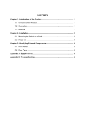
Introduction of the Product 1 1.1 Overview of the Product 1 1.2 Convention 1 1.3 Features...1 Chapter 2. Identifying External Components 3 3.1 Front Panel 3 3.2 Rear Panel 3 Appendix A: Specifications 4 Appendix B: Troubleshooting 5 CONTENTS Chapter 1. Installation 2 2.1 Mounting the Switch on a Desk 2 2.2 Power On 2 Chapter 3.
Introduction of the Product 1 1.1 Overview of the Product 1 1.2 Convention 1 1.3 Features...1 Chapter 2. Identifying External Components 3 3.1 Front Panel 3 3.2 Rear Panel 3 Appendix A: Specifications 4 Appendix B: Troubleshooting 5 CONTENTS Chapter 1. Installation 2 2.1 Mounting the Switch on a Desk 2 2.2 Power On 2 Chapter 3.
User Guide
Page 7
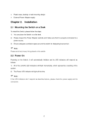
¾ Plastic case, desktop or wall-mounting design ¾ External Power Adapter supply Chapter 2. Installation 2.1 Mounting the Switch on a Desk To install the Switch, please follow the steps: 1) You can place the Switch on a flat desk. 2) Please inspect the Power Adapter carefully and make ... on the switch. 2.2 Power On Powering on the Switch, it will automatically initialize and its LED indicators will respond as follows: 1) All of the Link/Act LED indicators will flash momentarily, which represents a resetting of the system. 2) The Power LED indicator will light all the time. ) Note: If...
¾ Plastic case, desktop or wall-mounting design ¾ External Power Adapter supply Chapter 2. Installation 2.1 Mounting the Switch on a Desk To install the Switch, please follow the steps: 1) You can place the Switch on a flat desk. 2) Please inspect the Power Adapter carefully and make ... on the switch. 2.2 Power On Powering on the Switch, it will automatically initialize and its LED indicators will respond as follows: 1) All of the Link/Act LED indicators will flash momentarily, which represents a resetting of the system. 2) The Power LED indicator will light all the time. ) Note: If...