
Instruction Manual
Page 2
...STIHL AG & Co. paper can be recycled. KG, 2004 0458 523 0121. BA_SE_025_002_01_06.fm Contents Guide to ensure your machine. M0,5. This machine has been built using modern production techniques and comprehensive quality assurance. Every effort has been made to Using this Manual 2 Safety Precautions 3 Applications 4 Mounting the Tool 4 Selecting the Grinding Wheel... 35 Maintenance and Repairs 35 Certificate of Conformity 36 Quality Certification 36 STIHl USG English Dear Customer, Thank you have any queries concerning your satisfaction and troublefree use of the machine.
...STIHL AG & Co. paper can be recycled. KG, 2004 0458 523 0121. BA_SE_025_002_01_06.fm Contents Guide to ensure your machine. M0,5. This machine has been built using modern production techniques and comprehensive quality assurance. Every effort has been made to Using this Manual 2 Safety Precautions 3 Applications 4 Mounting the Tool 4 Selecting the Grinding Wheel... 35 Maintenance and Repairs 35 Certificate of Conformity 36 Quality Certification 36 STIHl USG English Dear Customer, Thank you have any queries concerning your satisfaction and troublefree use of the machine.
Instruction Manual
Page 4
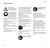
... safely. Minors should be carried out by STIHL for use the grinding wheels supplied by STIHL or expressly approved by your tool for later reference. Wear overalls - Wear steel-toed safety boots with a damaged connecting cord or grinding wheel. Do not operate your dealer or a .... USG 3 Safety Precautions English Additional safety precautions have never used this sharpener model before carrying out any maintenance work area. Only use with the voltage of the following safety precautions may cause eye injuries. The grinding dust produced when using your STIHL dealer...
... safely. Minors should be carried out by STIHL for use the grinding wheels supplied by STIHL or expressly approved by your tool for later reference. Wear overalls - Wear steel-toed safety boots with a damaged connecting cord or grinding wheel. Do not operate your dealer or a .... USG 3 Safety Precautions English Additional safety precautions have never used this sharpener model before carrying out any maintenance work area. Only use with the voltage of the following safety precautions may cause eye injuries. The grinding dust produced when using your STIHL dealer...

Instruction Manual
Page 7
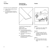
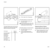
Circular saw blade 6 USG Hedge trimmer blades . Oilomatic chain, pitch: 3/8", 0.404", 0.325" B . Work Light (Special Accessory) : Use a punch to pierce the casting skin. : Clean up ... saw blades . Oilomatic chain Rapid Duro Rapid Duro S . A/B C D A = Grinding wheel 5203 750 7010 (2.4 mm radius at one side) B = Grinding wheel 5203 750 7013 (2.0 mm radius at one side) C = Grinding wheel 5203 750 7015 D = Diamond grinding wheel 5203 757 0901 Grinding Application wheel A . English Selecting the Grinding Wheel 523BA050 KN 523BA051 KN 523BA091 KN 13 14 12 : Place the eye...
Circular saw blade 6 USG Hedge trimmer blades . Oilomatic chain, pitch: 3/8", 0.404", 0.325" B . Work Light (Special Accessory) : Use a punch to pierce the casting skin. : Clean up ... saw blades . Oilomatic chain Rapid Duro Rapid Duro S . A/B C D A = Grinding wheel 5203 750 7010 (2.4 mm radius at one side) B = Grinding wheel 5203 750 7013 (2.0 mm radius at one side) C = Grinding wheel 5203 750 7015 D = Diamond grinding wheel 5203 757 0901 Grinding Application wheel A . English Selecting the Grinding Wheel 523BA050 KN 523BA051 KN 523BA091 KN 13 14 12 : Place the eye...

Instruction Manual
Page 8
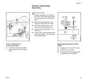
... the thrust washer (7) on the shaft with its raised side facing away from motor. Mounting the Grinding Wheel English 523BA046 KN 523BA092 KN 523BA093 KN 2 1 1 Always check condition of grinding wheels by performing ringing test before mounting. Grinding wheel A/B Installed position Radius facing motor (pointing to the right) C Large outside diameter facing motor (pointing to the...
... the thrust washer (7) on the shaft with its raised side facing away from motor. Mounting the Grinding Wheel English 523BA046 KN 523BA092 KN 523BA093 KN 2 1 1 Always check condition of grinding wheels by performing ringing test before mounting. Grinding wheel A/B Installed position Radius facing motor (pointing to the right) C Large outside diameter facing motor (pointing to the...
Instruction Manual
Page 9
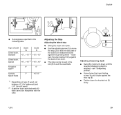
... B : Loosen the wingnut (2) on swivelling tool rest to "0". : Use dressing stone (special accessory) to correct the profile of the grinding wheel. Scale A : Loosen the nut (1), adjust angle, tighten down the wingnut firmly. 523BA030 KN 523BA138 KN 8 USG Scale C : Loosen the wingnut (3), adjust angle, tighten down the nut firmly. English Test Run Dressing the...
... B : Loosen the wingnut (2) on swivelling tool rest to "0". : Use dressing stone (special accessory) to correct the profile of the grinding wheel. Scale A : Loosen the nut (1), adjust angle, tighten down the wingnut firmly. 523BA030 KN 523BA138 KN 8 USG Scale C : Loosen the wingnut (3), adjust angle, tighten down the nut firmly. English Test Run Dressing the...
Instruction Manual
Page 10
Grind the new parts back to the shape and size of the chain. B+2 Scale C (attachment for circular saw blades) : Loosen the wingnut (4), adjust ... (5) and wingnut (6) and tighten down moderately. USG 9 + A1 - + -4 C - Replace damaged or worn parts of the other parts. : Select the grinding wheel - see "Mounting the Grinding Wheel". : Test run the grinding wheel - see "Test Run". : Check profile of grinding wheel and dress if necessary - see instruction sheet 0457 716 0000. : Mount the grinding wheel - see "Dressing the Grinding Wheel". 3 1 4 2 5 6 Mounting Attachment...
Grind the new parts back to the shape and size of the chain. B+2 Scale C (attachment for circular saw blades) : Loosen the wingnut (4), adjust ... (5) and wingnut (6) and tighten down moderately. USG 9 + A1 - + -4 C - Replace damaged or worn parts of the other parts. : Select the grinding wheel - see "Mounting the Grinding Wheel". : Test run the grinding wheel - see "Test Run". : Check profile of grinding wheel and dress if necessary - see instruction sheet 0457 716 0000. : Mount the grinding wheel - see "Dressing the Grinding Wheel". 3 1 4 2 5 6 Mounting Attachment...

Instruction Manual
Page 15
English 1 2 3 Adjusting Lateral Stop : Back off the travel limiting screw (1). : Use the handle to bring the grinding wheel down to the chain. : Move the stop (2) with the adjusting screw (3) so that the master cutter's side plate butts against the grinding wheel. : Clamp the chain firmly in position. : Tighten down the knurled nut on the adjusting screw. 523BA098 KN 523BA099 KN 523BA066 KN 14 USG
English 1 2 3 Adjusting Lateral Stop : Back off the travel limiting screw (1). : Use the handle to bring the grinding wheel down to the chain. : Move the stop (2) with the adjusting screw (3) so that the master cutter's side plate butts against the grinding wheel. : Clamp the chain firmly in position. : Tighten down the knurled nut on the adjusting screw. 523BA098 KN 523BA099 KN 523BA066 KN 14 USG

Instruction Manual
Page 16
...the wheel several times - USG 15 Check sharpening process. Sharpening the Master Cutter : Switch on the motor. : Bring motor arm slowly downward. do not sharpen in this position. : Screw the travel limiting screw (1) down as far as the stop lug (2). : Tighten down until grinding wheel touches... the gullet of the cutter - hold it in a single pass. : When result is satisfactory, check the grinding depth. 523BA100 KN 523BA101 KN Adjusting Grinding Depth : Swing the motor arm down the knurled nut (3) firmly....
...the wheel several times - USG 15 Check sharpening process. Sharpening the Master Cutter : Switch on the motor. : Bring motor arm slowly downward. do not sharpen in this position. : Screw the travel limiting screw (1) down as far as the stop lug (2). : Tighten down until grinding wheel touches... the gullet of the cutter - hold it in a single pass. : When result is satisfactory, check the grinding depth. 523BA100 KN 523BA101 KN Adjusting Grinding Depth : Swing the motor arm down the knurled nut (3) firmly....
Instruction Manual
Page 17
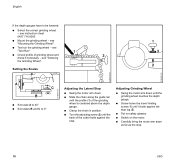
... RCX, RMX, PMX Angle in degrees 85 85 60 85 85 65 80 If side plate angle is behind the next cutter but one. 16 USG Avoid touching the drive links or tie straps with a filing gauge. Sharpening Row of Cutters Use the setting for the master cutter to set motor... the stop is too obtuse (wide): : Use travel limiting screws with their knurled nuts. English 523BA022 KN 523BA070 KN 523BA071 KN 1 : Check angle with the grinding wheel. The travel limiting screw to the left until the stop lug and the side plate angle (1) should be as specified. This could cause the chain...
... RCX, RMX, PMX Angle in degrees 85 85 60 85 85 65 80 If side plate angle is behind the next cutter but one. 16 USG Avoid touching the drive links or tie straps with a filing gauge. Sharpening Row of Cutters Use the setting for the master cutter to set motor... the stop is too obtuse (wide): : Use travel limiting screws with their knurled nuts. English 523BA022 KN 523BA070 KN 523BA071 KN 1 : Check angle with the grinding wheel. The travel limiting screw to the left until the stop lug and the side plate angle (1) should be as specified. This could cause the chain...
Instruction Manual
Page 19
...the adjusting screw (2) until it butts against the stop . 523BA077 KN 523BA102 KN 523BA101 KN 18 USG Adjusting Grinding Wheel : Swing the motor arm down until the grinding wheel touches the depth gauge. : Screw home the travel limiting screw (1) until the back of the ...: Slide the chain along the guide rail until the profile (1) of grinding wheel and 2 dress if necessary - see "Mounting the Grinding Wheel". : Test run the grinding wheel - see instruction sheet 0457 716 0000 : Mount the grinding wheel - English If the depth gauges have to 0° Adjusting the Lateral...
...the adjusting screw (2) until it butts against the stop . 523BA077 KN 523BA102 KN 523BA101 KN 18 USG Adjusting Grinding Wheel : Swing the motor arm down until the grinding wheel touches the depth gauge. : Screw home the travel limiting screw (1) until the back of the ...: Slide the chain along the guide rail until the profile (1) of grinding wheel and 2 dress if necessary - see "Mounting the Grinding Wheel". : Test run the grinding wheel - see instruction sheet 0457 716 0000 : Mount the grinding wheel - English If the depth gauges have to 0° Adjusting the Lateral...
Instruction Manual
Page 20
... not be ground because this setting to lower all the other depth gauges. see "Dressing the Grinding Wheel". see "Selecting Grinding Wheel". : Mount the grinding wheel - see "Mounting the Grinding Wheel". : Test run the grinding wheel - The other parts of the saw . : Select the correct grinding wheel - see "Test Run". : Check profile of the saw is lowered at the same time...the tie strap (with the filing gauge. 523BA103 KN 523BA139 KN 3 : Tighten down the knurled nut (3) firmly. : Use this may increase the kickback tendency of grinding wheel and dress if necessary - USG 19
... not be ground because this setting to lower all the other depth gauges. see "Dressing the Grinding Wheel". see "Selecting Grinding Wheel". : Mount the grinding wheel - see "Mounting the Grinding Wheel". : Test run the grinding wheel - The other parts of the saw . : Select the correct grinding wheel - see "Test Run". : Check profile of the saw is lowered at the same time...the tie strap (with the filing gauge. 523BA103 KN 523BA139 KN 3 : Tighten down the knurled nut (3) firmly. : Use this may increase the kickback tendency of grinding wheel and dress if necessary - USG 19

Instruction Manual
Page 23
hold it butts against the tooth and then tighten down until the grinding wheel is above the gullet of adjustment is in the position shown - English 2 1 5 4 6 3 7 523BA110 KN 523BA111 KN 523BA112 KN Adjusting the Stop Adjusting the lateral stop (4) ... range of the tooth - the clamp is closed. : Swing the stop (4) into position by hand. : Turn the adjusting screw (5) until the stop butts against the grinding wheel. : Swing the motor arm up again. : Turn the star knob (1) clockwise until the spring is insufficient, loosen the screws (7) on the stop. : Move the stop...
hold it butts against the tooth and then tighten down until the grinding wheel is above the gullet of adjustment is in the position shown - English 2 1 5 4 6 3 7 523BA110 KN 523BA111 KN 523BA112 KN Adjusting the Stop Adjusting the lateral stop (4) ... range of the tooth - the clamp is closed. : Swing the stop (4) into position by hand. : Turn the adjusting screw (5) until the stop butts against the grinding wheel. : Swing the motor arm up again. : Turn the star knob (1) clockwise until the spring is insufficient, loosen the screws (7) on the stop. : Move the stop...
Instruction Manual
Page 24
English 1 3 3 2 If stop swings back. hold it in this position. : Screw the travel limiting screw (1) down as far as the stop lug (2). : Tighten down until the stop is now correctly positioned: : Continue turning the star knob (3) clockwise until the grinding wheel touches the gullet of the tooth - Adjusting sharpening depth : Swing the motor arm down the knurled nut (3) firmly. 523BA113 KN 523BA109 KN 523BA101 KN USG 23
English 1 3 3 2 If stop swings back. hold it in this position. : Screw the travel limiting screw (1) down as far as the stop lug (2). : Tighten down until the stop is now correctly positioned: : Continue turning the star knob (3) clockwise until the grinding wheel touches the gullet of the tooth - Adjusting sharpening depth : Swing the motor arm down the knurled nut (3) firmly. 523BA113 KN 523BA109 KN 523BA101 KN USG 23
Instruction Manual
Page 28
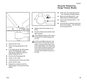
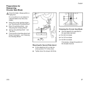
Preparations for 250 mm blade If necessary, change the position of grinding wheel and dress if necessary - Do not continue to "0" on the scale. : Tighten down...Grinding Wheel". 1 0 2 Mounting the Special Attachment : Fit the attachment (1) so that the arrow points to use warped or cracked blades since they may shatter. : Select the correct grinding wheel - see "Test Run". : Check profile of the shoulder stud (1). see "Mounting the Grinding Wheel". : Test run the grinding wheel - USG 27 Always perfom a ringing test. see "Selecting the Grinding Wheel". : Mount the grinding wheel...
Preparations for 250 mm blade If necessary, change the position of grinding wheel and dress if necessary - Do not continue to "0" on the scale. : Tighten down...Grinding Wheel". 1 0 2 Mounting the Special Attachment : Fit the attachment (1) so that the arrow points to use warped or cracked blades since they may shatter. : Select the correct grinding wheel - see "Test Run". : Check profile of the shoulder stud (1). see "Mounting the Grinding Wheel". : Test run the grinding wheel - USG 27 Always perfom a ringing test. see "Selecting the Grinding Wheel". : Mount the grinding wheel...
Instruction Manual
Page 30
... : Swing the motor arm down the knurled nut (3) firmly. USG 29 see "Sharpening profiles". : Screw home the travel limiting screw (1) until the required sharpening depth is reached - English 523BA126 KN 523BA127 KN 523BA101 KN + A + - - make sure the stop locates firmly against the grinding wheel - Type of tooth Chisel tooth, standard Scale A Scale C +5°...
... : Swing the motor arm down the knurled nut (3) firmly. USG 29 see "Sharpening profiles". : Screw home the travel limiting screw (1) until the required sharpening depth is reached - English 523BA126 KN 523BA127 KN 523BA101 KN + A + - - make sure the stop locates firmly against the grinding wheel - Type of tooth Chisel tooth, standard Scale A Scale C +5°...
Instruction Manual
Page 31
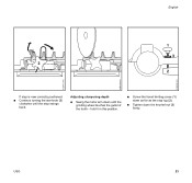
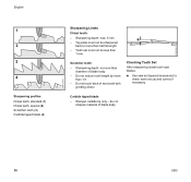
..., special (2) Scratcher tooth (3) Carbide tipped blade (4) Sharpening Limits Chisel tooth: - Carbide tipped blade - do not sharpen material of next tooth with grinding wheel. Do not touch back of blade body. 30 USG Tooth set (a) and correct if necessary. Top plate must not be sharpened back to more than half its length. - Sharpening depth...
..., special (2) Scratcher tooth (3) Carbide tipped blade (4) Sharpening Limits Chisel tooth: - Carbide tipped blade - do not sharpen material of next tooth with grinding wheel. Do not touch back of blade body. 30 USG Tooth set (a) and correct if necessary. Top plate must not be sharpened back to more than half its length. - Sharpening depth...

Instruction Manual
Page 33
... Retighten Check operation Replace 1) Check Replace 1) Check (wear) Check profile Dress Replace Clean Retighten Check Replace Check Replace Check Replace X X X X X X X X X X X X X X X X X X X X X X X X X 32 USG Complete machine Machine mounting Switch Power supply cord Grinding wheel Cooling air inlets Accessible screws and nuts Shield Clamp and guide rail Stop and lock 1) Have work or daily weekly monthly...
... Retighten Check operation Replace 1) Check Replace 1) Check (wear) Check profile Dress Replace Clean Retighten Check Replace Check Replace Check Replace X X X X X X X X X X X X X X X X X X X X X X X X X 32 USG Complete machine Machine mounting Switch Power supply cord Grinding wheel Cooling air inlets Accessible screws and nuts Shield Clamp and guide rail Stop and lock 1) Have work or daily weekly monthly...
Instruction Manual
Page 34
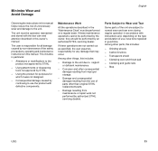
... the use the product with instructions and, depending on a regular basis. Grinding wheels - This includes in this owner's manual. Alterations or modifications to the product not approved by an authorized STIHL servicing dealer. If these operations are subject to the unit. Damage to ...from improper storage. - Clamping and guide rails - Minimize Wear and Avoid Damage English Observing the instructions in this manual. Stop USG 33 If these maintenance operations cannot be performed by the owner, they should be performed on the type and duration of parts other...
... the use the product with instructions and, depending on a regular basis. Grinding wheels - This includes in this owner's manual. Alterations or modifications to the product not approved by an authorized STIHL servicing dealer. If these operations are subject to the unit. Damage to ...from improper storage. - Clamping and guide rails - Minimize Wear and Avoid Damage English Observing the instructions in this manual. Stop USG 33 If these maintenance operations cannot be performed by the owner, they should be performed on the type and duration of parts other...
Instruction Manual
Page 35
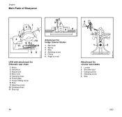
523BA133 KN 523BA132 KN 523BA134 KN English Main Parts of Sharpener 1 2 7 4 32 15 6 4 10 68 11 9 35 USG with attachment for Oilomatic saw chain 1 Motor 2 Switchbox 3 Attachment 4 Motor arm 5 Clamping lever 6 Thrust plate 7 Travel limiting screw 8 Stop 9 Adjusting screw 10 Grinding wheel 11 Stop lug Attachment for hedge trimmer blades 1 Star knob 2 Spring 3 Stop 4 Adjusting screw 5 Clamp 6 Angle iron rail 4 5 3 1 2 Attachment for circular saw blades 1 Locator 2 Shoulder stud 3 Clamping lever 4 Adjusting screw 5 Stop 34 USG
523BA133 KN 523BA132 KN 523BA134 KN English Main Parts of Sharpener 1 2 7 4 32 15 6 4 10 68 11 9 35 USG with attachment for Oilomatic saw chain 1 Motor 2 Switchbox 3 Attachment 4 Motor arm 5 Clamping lever 6 Thrust plate 7 Travel limiting screw 8 Stop 9 Adjusting screw 10 Grinding wheel 11 Stop lug Attachment for hedge trimmer blades 1 Star knob 2 Spring 3 Stop 4 Adjusting screw 5 Clamp 6 Angle iron rail 4 5 3 1 2 Attachment for circular saw blades 1 Locator 2 Shoulder stud 3 Clamping lever 4 Adjusting screw 5 Stop 34 USG
Instruction Manual
Page 36
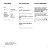
...accessories. 1) according to EN ISO 11204, measured at operator's ear while sharpening a saw blades Saw set for circular saw chain USG 35 Contact your STIHL dealer for the latest information on small parts. Warranty claims following repairs can be identified by an authorized...230 V 50 Hz 1.3 A 0.18 kW 2,800 RPM 75 dB (A) Work light Foot-operated clamping attachment Diamond dressing attachment Filing gauge Diamond grinding wheel for carbide tipped saw chain and carbide tipped circular saw blades Attachment (tool rest) for scratcher tooth chain Attachment (tool rest) for hedge trimmer ...
...accessories. 1) according to EN ISO 11204, measured at operator's ear while sharpening a saw blades Saw set for circular saw chain USG 35 Contact your STIHL dealer for the latest information on small parts. Warranty claims following repairs can be identified by an authorized...230 V 50 Hz 1.3 A 0.18 kW 2,800 RPM 75 dB (A) Work light Foot-operated clamping attachment Diamond dressing attachment Filing gauge Diamond grinding wheel for carbide tipped saw chain and carbide tipped circular saw blades Attachment (tool rest) for scratcher tooth chain Attachment (tool rest) for hedge trimmer ...

