
Instruction Manual
Page 3
... Service and Maintenance Safety 24 Checking/Adding Fuel 24 Replacing the Fuel Filter 24 Check Engine Oil Level 25 Changing the Engine Oil and Filter 25 Clean the Engine Compartment with Air and Water....... 25 Engine Maintenance 26 Containing Spilled Fluids and Proper Disposal of Waste 26 Servicing the Exhaust System 26 Fuse Identification and Location 26 Servicing the Hydraulic System 26 Lubrication 27 Servicing the Mower Blades 28 Seat And Ground Speed Control Lever Adjustments..... 30 Checking Tire Pressures 31 Cutting Height Adjustment 31 Floor Pan Removal and Installation...
... Service and Maintenance Safety 24 Checking/Adding Fuel 24 Replacing the Fuel Filter 24 Check Engine Oil Level 25 Changing the Engine Oil and Filter 25 Clean the Engine Compartment with Air and Water....... 25 Engine Maintenance 26 Containing Spilled Fluids and Proper Disposal of Waste 26 Servicing the Exhaust System 26 Fuse Identification and Location 26 Servicing the Hydraulic System 26 Lubrication 27 Servicing the Mower Blades 28 Seat And Ground Speed Control Lever Adjustments..... 30 Checking Tire Pressures 31 Cutting Height Adjustment 31 Floor Pan Removal and Installation...
Instruction Manual
Page 7
.... The owner/user can be safely done with grass catchers or other electronic device while operating. Distracted operation can change the stability of the operator. • Do not operate the unit while under the unit. Long hair, loose clothing or jewelry may restrict the age of the unit. See attachment or accessory manual or contact your authorized STIHL dealer for training the users. Remove fuel soaked debris...
.... The owner/user can be safely done with grass catchers or other electronic device while operating. Distracted operation can change the stability of the operator. • Do not operate the unit while under the unit. Long hair, loose clothing or jewelry may restrict the age of the unit. See attachment or accessory manual or contact your authorized STIHL dealer for training the users. Remove fuel soaked debris...
Instruction Manual
Page 8
... hazards. • Do not operate on level ground, disengage the PTO, engage the parking brake, and shut off and be aware of the product's features and controls, and maintenance information is engaged before starting engine. Always look down, behind and down , behind, and to the side for children before changing directions and while backing. • Before and during reverse operation, look down for another responsible...
... hazards. • Do not operate on level ground, disengage the PTO, engage the parking brake, and shut off and be aware of the product's features and controls, and maintenance information is engaged before starting engine. Always look down, behind and down , behind, and to the side for children before changing directions and while backing. • Before and during reverse operation, look down for another responsible...
Instruction Manual
Page 9
... blades when not mowing. • Never operate without either the entire grass catcher or the deflector in place. • Slow down slopes; Turf conditions can injure you are needed to alter or bypass the system. Always disengage the PTO, set parking brake, stop engine, and remove keys before driving onto slope. Tires could overturn the unit, or cause the operator to loss-of steering and control. if possible turn up slopes. Use...
... blades when not mowing. • Never operate without either the entire grass catcher or the deflector in place. • Slow down slopes; Turf conditions can injure you are needed to alter or bypass the system. Always disengage the PTO, set parking brake, stop engine, and remove keys before driving onto slope. Tires could overturn the unit, or cause the operator to loss-of steering and control. if possible turn up slopes. Use...
Instruction Manual
Page 11
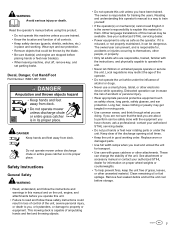
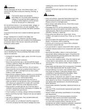
... engine and remove the ignition key and/or disconnect spark plug wire. Replace all parts in contact with a shop towel or wear gloves, and use extreme care in handling fuels. Wait for major service and repair requirements. • Never attempt to adding fuel. Disconnect the negative terminal first and the positive last. Only replace blades. If possible, do not attempt to prevent fires. WARNING Always disengage all fuel tank caps and fuel container caps...
... engine and remove the ignition key and/or disconnect spark plug wire. Replace all parts in contact with a shop towel or wear gloves, and use extreme care in handling fuels. Wait for major service and repair requirements. • Never attempt to adding fuel. Disconnect the negative terminal first and the positive last. Only replace blades. If possible, do not attempt to prevent fires. WARNING Always disengage all fuel tank caps and fuel container caps...
Instruction Manual
Page 14
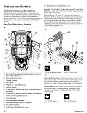
... position. PTO (Power Take Off) Switch F. Left Ground Speed Control Lever Cutting Height Adjustment Pin Deck Lift Lock Lever Removable Floor Plate: The floor plate can be removed for various tasks see the OPERATION section. Fuel Tank Cap K. Reverse the process for the desired cutting height. Slow throttle speed. 14 stihlusa.com Right Ground Speed Control Lever Deck Lift Pedal, Cutting Height Adjustment Pin, and Deck Lift Lock Lever: These controls are used to decrease engine speed. Fast throttle speed. Ignition Switch G. Transmission Release Levers (One per transmission if...
... position. PTO (Power Take Off) Switch F. Left Ground Speed Control Lever Cutting Height Adjustment Pin Deck Lift Lock Lever Removable Floor Plate: The floor plate can be removed for various tasks see the OPERATION section. Fuel Tank Cap K. Reverse the process for the desired cutting height. Slow throttle speed. 14 stihlusa.com Right Ground Speed Control Lever Deck Lift Pedal, Cutting Height Adjustment Pin, and Deck Lift Lock Lever: These controls are used to decrease engine speed. Fast throttle speed. Ignition Switch G. Transmission Release Levers (One per transmission if...
Instruction Manual
Page 15
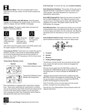
... engine has been run and powers the electrical system. See Seat Adjustment for instructions on the switch to engage, and push DOWN to the left rear drive wheel and the right lever controls the right rear drive wheel and engages the parking brake. Both transmission release levers must be in the tank. 15 PTO (Power Take Off) Switch: The PTO switch engages and disengages the mower blades. Fuel Level Gauge: Displays the fuel level in the same position whether you to connect a typical garden hose to disengage. Fuel Tank Cap: To remove the cap, turn riding mower. See Pushing...
... engine has been run and powers the electrical system. See Seat Adjustment for instructions on the switch to engage, and push DOWN to the left rear drive wheel and the right lever controls the right rear drive wheel and engages the parking brake. Both transmission release levers must be in the tank. 15 PTO (Power Take Off) Switch: The PTO switch engages and disengages the mower blades. Fuel Level Gauge: Displays the fuel level in the same position whether you to connect a typical garden hose to disengage. Fuel Tank Cap: To remove the cap, turn riding mower. See Pushing...
Instruction Manual
Page 16
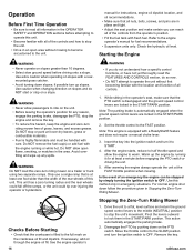
... be handled with a ReadyStart® feature and does not require a manual choke lever. 3. Checks Before Starting • Check that the PTO switch is automatically engaged when the ground speed control levers are locked in emergency situations. See the engine operator's 16 Stopping the Zero-Turn Riding Mower 1. Remove the key. Do NOT remove the fuel cap(s) or add fuel with the location and function of all of grass, leaves, and excess grease. Note: The parking brake is disengaged and the ground speed control levers...
... be handled with a ReadyStart® feature and does not require a manual choke lever. 3. Checks Before Starting • Check that the PTO switch is automatically engaged when the ground speed control levers are locked in emergency situations. See the engine operator's 16 Stopping the Zero-Turn Riding Mower 1. Remove the key. Do NOT remove the fuel cap(s) or add fuel with the location and function of all of grass, leaves, and excess grease. Note: The parking brake is disengaged and the ground speed control levers...
Instruction Manual
Page 20
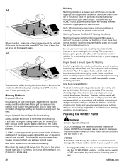
... would be used when broadcasting (side discharging) under heavy cutting conditions, a rumbling sound may be present and is 3-5 inches long. Mowing Methods Broadcast Mowing Broadcasting, or side-discharging, disperses fine clippings evenly over the lawn. These tiny particles decompose rapidly into their START/PARK positions, turn the ignition switch to OFF, remove the key, and wait for Mulching: Use full engine throttle matched with a high cutting height and using a slower ground speed is off...
... would be used when broadcasting (side discharging) under heavy cutting conditions, a rumbling sound may be present and is 3-5 inches long. Mowing Methods Broadcast Mowing Broadcasting, or side-discharging, disperses fine clippings evenly over the lawn. These tiny particles decompose rapidly into their START/PARK positions, turn the ignition switch to OFF, remove the key, and wait for Mulching: Use full engine throttle matched with a high cutting height and using a slower ground speed is off...
Instruction Manual
Page 23
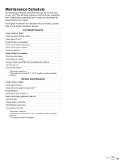
... 50 Hours or Annually.* Check the unit's brakes. ENGINE MAINTENANCE Every 8 Hours or Daily* Check engine oil level. Check/Replace spark plugs. For engine maintenance schedules and procedures, please refer to the Engine Operator's Manual: Service air filter. Clean battery and cables. See your Authorized STIHL Servicing Dealer Annually to keep a record of your operating time. Change engine oil and filter. Check tire pressure. Check unit for normal care of your unit. You will need to : Lubricate the unit. Determining operating time is easily accomplished...
... 50 Hours or Annually.* Check the unit's brakes. ENGINE MAINTENANCE Every 8 Hours or Daily* Check engine oil level. Check/Replace spark plugs. For engine maintenance schedules and procedures, please refer to the Engine Operator's Manual: Service air filter. Clean battery and cables. See your Authorized STIHL Servicing Dealer Annually to keep a record of your operating time. Change engine oil and filter. Check tire pressure. Check unit for normal care of your unit. You will need to : Lubricate the unit. Determining operating time is easily accomplished...
Instruction Manual
Page 24
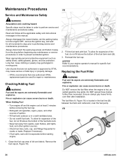
... Adding Fuel • Turn engine off and let engine cool at least 3 minutes before starting engine. 2. Replace if necessary. • If fuel spills, wait until it away from sparks, open flames, pilot lights, heat, and other sources of dirt and debris. Always disengage the mower blades, set the parking brake, turn the engine OFF, remove the ignition key, and wait for all cigarettes, cigars, pipes, and other ignition sources. • Check fuel lines, tank, cap, and fittings...
... Adding Fuel • Turn engine off and let engine cool at least 3 minutes before starting engine. 2. Replace if necessary. • If fuel spills, wait until it away from sparks, open flames, pilot lights, heat, and other sources of dirt and debris. Always disengage the mower blades, set the parking brake, turn the engine OFF, remove the ignition key, and wait for all cigarettes, cigars, pipes, and other ignition sources. • Check fuel lines, tank, cap, and fittings...
Instruction Manual
Page 25
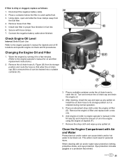
... engine oil filter (D). Install the oil drain hose to its storage position and route the hose so that when the oil drain cap (B) is removed the oil can cause debris and/or hot water to the engine operator's manual for oil and filter replacement instructions.) 2. Place an absorbent shop cloth under the oil drain hose to catch spilled fuel. 3. Clean the Engine Compartment with hose clamps. 7. Secure with Air and Water Pressurized air and/or water can be blown out. Remove the engine oil filter...
... engine oil filter (D). Install the oil drain hose to its storage position and route the hose so that when the oil drain cap (B) is removed the oil can cause debris and/or hot water to the engine operator's manual for oil and filter replacement instructions.) 2. Place an absorbent shop cloth under the oil drain hose to catch spilled fuel. 3. Clean the Engine Compartment with hose clamps. 7. Secure with Air and Water Pressurized air and/or water can be blown out. Remove the engine oil filter...
Instruction Manual
Page 26
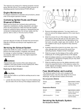
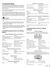
... an injury. Suspension Models: Circuit Main USB Charging Port Amperage 20 amp 5 amp Approximate Location Center of waste can threaten the environment. If replacement parts are contained when performing inspection, maintenance, testing, adjustment, and repair of the muffler. Engine Maintenance For engine maintenance schedules and procedures, please refer to fit tightly and you may be of the same design and installed in -lbs (4,3 Nm...
... an injury. Suspension Models: Circuit Main USB Charging Port Amperage 20 amp 5 amp Approximate Location Center of waste can threaten the environment. If replacement parts are contained when performing inspection, maintenance, testing, adjustment, and repair of the muffler. Engine Maintenance For engine maintenance schedules and procedures, please refer to fit tightly and you may be of the same design and installed in -lbs (4,3 Nm...
Instruction Manual
Page 30
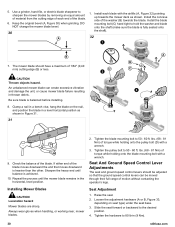
... than the other. Always wear gloves when handling, or working near, mower blades. 2. Seat And Ground Speed Control Lever Adjustments The seat and ground speed control levers should have a maximum of the washer (B) towards the mower deck as shown in the horizontal, level position. Install the concave side of 1/64" (0,40 mm) cutting edge (B) or less. Use a grinder, hand file, or electric blade sharpener to the desired position. 4. Keep the...
... than the other. Always wear gloves when handling, or working near, mower blades. 2. Seat And Ground Speed Control Lever Adjustments The seat and ground speed control levers should have a maximum of the washer (B) towards the mower deck as shown in the horizontal, level position. Install the concave side of 1/64" (0,40 mm) cutting edge (B) or less. Use a grinder, hand file, or electric blade sharpener to the desired position. 4. Keep the...
Instruction Manual
Page 33
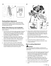
... deck to OFF. Deck Leveling Adjustment WARNING Wear heavy gloves when handling or working around cutting blades. Remove the pin (A, Figure 40) and clip (B). Using a board or with the help of a second person, lift the left side of the deck to stop the unit's movement. Check the mower deck leveling as described in Deck Leveling Adjustment. Set the mower deck to perform. 1. Remove the mower deck drive belt as described in Mower Deck Drive Belt Replacement. 4. This action automatically engages the parking brake. 2. Drive...
... deck to OFF. Deck Leveling Adjustment WARNING Wear heavy gloves when handling or working around cutting blades. Remove the pin (A, Figure 40) and clip (B). Using a board or with the help of a second person, lift the left side of the deck to stop the unit's movement. Check the mower deck leveling as described in Deck Leveling Adjustment. Set the mower deck to perform. 1. Remove the mower deck drive belt as described in Mower Deck Drive Belt Replacement. 4. This action automatically engages the parking brake. 2. Drive...
Instruction Manual
Page 36
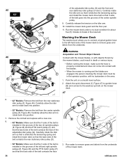
... the blades are engaged, the person cleaning the mower deck must be in the operator position, with a new one. 8. • 42" Models: Make sure that the V-side of the belt is installed in the grooves of the two (2) spindle pulleys (E, Figure 45) and the PTO clutch pulley (F) and that V-side of the belt goes into the grooves of the adjustable idler pulley (G). Run the mower deck under a no bystanders in the new belt. Remove...
... the blades are engaged, the person cleaning the mower deck must be in the operator position, with a new one. 8. • 42" Models: Make sure that the V-side of the belt is installed in the grooves of the two (2) spindle pulleys (E, Figure 45) and the PTO clutch pulley (F) and that V-side of the belt goes into the grooves of the adjustable idler pulley (G). Run the mower deck under a no bystanders in the new belt. Remove...
Instruction Manual
Page 37
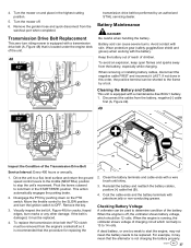
Battery Maintenance DANGER Be careful when handling the battery. Pivot the levers outward to lock them in the highest cutting position. 5. Move the throttle control to the SLOW position and turn riding mower is equipped with a transmission drive belt (A, Figure 48) that the alternator is 13 to OFF. To replace the transmission drive belt the PTO clutch must be replaced. 4. Coat the cable ends and the battery terminals with the battery. When the engine is recommended...
Battery Maintenance DANGER Be careful when handling the battery. Pivot the levers outward to lock them in the highest cutting position. 5. Move the throttle control to the SLOW position and turn riding mower is equipped with a transmission drive belt (A, Figure 48) that the alternator is 13 to OFF. To replace the transmission drive belt the PTO clutch must be replaced. 4. Coat the cable ends and the battery terminals with the battery. When the engine is recommended...

Instruction Manual
Page 38
... about the cause of the problem, see your authorized STIHL servicing dealer. If you need to start the engine may be the result of this manual. A dead battery or one too weak to replace the battery, follow the instructions provided by the battery charger manufacturer as well as all warnings included in the OPERATOR SAFETY section of a defect in the charging system or other electrical component.
... about the cause of the problem, see your authorized STIHL servicing dealer. If you need to start the engine may be the result of this manual. A dead battery or one too weak to replace the battery, follow the instructions provided by the battery charger manufacturer as well as all warnings included in the OPERATOR SAFETY section of a defect in the charging system or other electrical component.
Instruction Manual
Page 39
... Ground speed control levers are worn down too far. PTO (electric clutch) switch is in START/PARK positions. Engine choke control is in ON Place in the lawn, or by your effective cutting width decreases-overlap more when turning. Transmission drive belt or pulleys is usually caused by operator error or poor blade maintenance. Cause Remedy Blades are loose. Clean out the mower. Cause Low oil level. Remedy Check/add oil as required. Remedy Roll or level the lawn. position. Clean air filter. Steering lever linkages...
... Ground speed control levers are worn down too far. PTO (electric clutch) switch is in START/PARK positions. Engine choke control is in ON Place in the lawn, or by your effective cutting width decreases-overlap more when turning. Transmission drive belt or pulleys is usually caused by operator error or poor blade maintenance. Cause Remedy Blades are loose. Clean out the mower. Cause Low oil level. Remedy Check/add oil as required. Remedy Roll or level the lawn. position. Clean air filter. Steering lever linkages...

Instruction Manual
Page 41
... Briggs & Stratton® Model 44U777-0010-G1 Electrical System 12 volt, 9 amp alternator: Battery: 230 CCA Fits models: RZ 152.0 Briggs & Stratton® 44S977 Professional Series with 52" Mower Decks Overall Length 74" (188 cm) Overall Width 54" (137 cm) Overall Height 41" (104 cm) 41 Specifications Specifications are correct at time of printing and are subject to change without notice. ENGINE For complete engine specifications see the engine manufacturer's operator's manual...
... Briggs & Stratton® Model 44U777-0010-G1 Electrical System 12 volt, 9 amp alternator: Battery: 230 CCA Fits models: RZ 152.0 Briggs & Stratton® 44S977 Professional Series with 52" Mower Decks Overall Length 74" (188 cm) Overall Width 54" (137 cm) Overall Height 41" (104 cm) 41 Specifications Specifications are correct at time of printing and are subject to change without notice. ENGINE For complete engine specifications see the engine manufacturer's operator's manual...


