

Instruction Manual
Page 46
...system should always begin at the spark plug, b 3.5 - High voltage output with washers. : Remove the ground wire (4). - MS 231, MS 231 C, MS 251, MS 251 C 45 Troubleshooting on the ignition system. Connector tag for the short circuit wire. : Take out the screw (1). : Check the...- Remove the fan housing, b 8.2 1 7.1 Ignition Timing Ignition timing is obtained (after checking that wiring and stop switch are two electrical connections on the coil body: 1. Ignition System Exercise extreme caution when troubleshooting and carrying out maintenance or repair work . The high voltages ...
...system should always begin at the spark plug, b 3.5 - High voltage output with washers. : Remove the ground wire (4). - MS 231, MS 231 C, MS 251, MS 251 C 45 Troubleshooting on the ignition system. Connector tag for the short circuit wire. : Take out the screw (1). : Check the...- Remove the fan housing, b 8.2 1 7.1 Ignition Timing Ignition timing is obtained (after checking that wiring and stop switch are two electrical connections on the coil body: 1. Ignition System Exercise extreme caution when troubleshooting and carrying out maintenance or repair work . The high voltages ...
Instruction Manual
Page 48
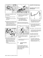
... 4503 2310RA123 TG 2310RA125 TG 165RA183 TG 3 2 Crimped side of ignition lead, see illustration. Crank the engine quickly with the aid of electric shock. - If a spark is visible, the ignition system is in retainer (4) until it snaps into position. - Note installed position of... : Push the ignition lead (2) fully into the slot (arrow) until it down firmly. : Connect spark plug boot to ignition timing. MS 231, MS 231 C, MS 251, MS 251 C 47 risk of the troubleshooting chart, b 7.8 7.4 Testing the Ignition Module To test the ignition module, use either the ZAT 4 ignition...
... 4503 2310RA123 TG 2310RA125 TG 165RA183 TG 3 2 Crimped side of ignition lead, see illustration. Crank the engine quickly with the aid of electric shock. - If a spark is visible, the ignition system is in retainer (4) until it snaps into position. - Note installed position of... : Push the ignition lead (2) fully into the slot (arrow) until it down firmly. : Connect spark plug boot to ignition timing. MS 231, MS 231 C, MS 251, MS 251 C 47 risk of the troubleshooting chart, b 7.8 7.4 Testing the Ignition Module To test the ignition module, use either the ZAT 4 ignition...

Instruction Manual
Page 49
... high voltage connection (2), ground connection (5) and the ground terminal (1). Installing 165RA184 TG 165RA188 TG 23 4 - High voltage - Crank the engine quickly with STIHL press fluid, b 14 : Hold the ignition lead and leg spring together and push them into the pierced hole in a safe place. If a spark is... and ignition lead (2) form a unit. If the ignition module is visible in the window (3), the ignition system is damaged. - risk of electric shock. : Use suitable pliers to pierce the center of the leg spring into the spark plug boot. 48 MS 231, MS 231 C, MS 251, MS 251 C
... high voltage connection (2), ground connection (5) and the ground terminal (1). Installing 165RA184 TG 165RA188 TG 23 4 - High voltage - Crank the engine quickly with STIHL press fluid, b 14 : Hold the ignition lead and leg spring together and push them into the pierced hole in a safe place. If a spark is... and ignition lead (2) form a unit. If the ignition module is visible in the window (3), the ignition system is damaged. - risk of electric shock. : Use suitable pliers to pierce the center of the leg spring into the spark plug boot. 48 MS 231, MS 231 C, MS 251, MS 251 C

Instruction Manual
Page 111
Description 1 Punch-down screws with electric or pneumatic screwdrivers; 13. Existing Special Tools No. Description 1 Carburetor and engine tester - Hose for leakage test 2 Sealing plate 3 Installing tool 4 Locking strip 5 .../ignition side) Spark plug 1) Protecting the oil seal (ignition side) Clamping machine to assembly stand Testing ignition system Testing ignition system 110 MS 231, MS 231 C, MS 251, MS 251 C Testing engine and carburetor for leaks Testing carburetor for leaks Testing carburetor for leaks Testing engine for assembly stand 17 Ignition system tester, ...
Description 1 Punch-down screws with electric or pneumatic screwdrivers; 13. Existing Special Tools No. Description 1 Carburetor and engine tester - Hose for leakage test 2 Sealing plate 3 Installing tool 4 Locking strip 5 .../ignition side) Spark plug 1) Protecting the oil seal (ignition side) Clamping machine to assembly stand Testing ignition system Testing ignition system 110 MS 231, MS 231 C, MS 251, MS 251 C Testing engine and carburetor for leaks Testing carburetor for leaks Testing carburetor for leaks Testing engine for assembly stand 17 Ignition system tester, ...


