

Instruction Manual
Page 2
... AV Spring on Fuel Tank 66 AV Spring on Handlebar 67 Stop Buffers 68 Buffers on Machines with Manual Fuel Pump 85 12.5 Carburetor 88 12.5.1 Leakage Test 89 RA_737_00_01_01 MS 231, MS 231 C, MS 251, MS 251 C q © ANDREAS STIHL AG & Co. QuickStop Super 75 10.3.3 Choke Rod 76 10.3.4 Throttle Rod 76 11. Models with QuickStop...
... AV Spring on Fuel Tank 66 AV Spring on Handlebar 67 Stop Buffers 68 Buffers on Machines with Manual Fuel Pump 85 12.5 Carburetor 88 12.5.1 Leakage Test 89 RA_737_00_01_01 MS 231, MS 231 C, MS 251, MS 251 C q © ANDREAS STIHL AG & Co. QuickStop Super 75 10.3.3 Choke Rod 76 10.3.4 Throttle Rod 76 11. Models with QuickStop...
Instruction Manual
Page 3
... and Installing 100 12.11 Fuel Intake 101 12.11.1 Pickup Body 101 12.11.2 Fuel Hose 101 12.11.3 Fuel Hoses - Servicing Aids 112 2 MS 231, MS 231 C, MS 251, MS 251 C Special Servicing Tools 110 14. Manual Fuel Pump 105 12.11.4 Manual Fuel Pump 107 12.11.5 Tank Housing 108 13.
... and Installing 100 12.11 Fuel Intake 101 12.11.1 Pickup Body 101 12.11.2 Fuel Hose 101 12.11.3 Fuel Hoses - Servicing Aids 112 2 MS 231, MS 231 C, MS 251, MS 251 C Special Servicing Tools 110 14. Manual Fuel Pump 105 12.11.4 Manual Fuel Pump 107 12.11.5 Tank Housing 108 13.

Instruction Manual
Page 4
... 2710RA320 TG 1.1 Introduction This service manual contains detailed descriptions of this manual. To help locate the fault, consult the chapter on "Troubleshooting" and the "STIHL Service Training System" for engineering changes which have several causes. The manual lists all the repair and servicing ... parts lists while carrying out repair work. MS 231, MS 231 C, MS 251, MS 251 C 3 1. You should make use of any replacement parts. The special tools mentioned in the descriptions are as shown in the "STIHL Special Tools" manual. The meanings are listed in the chapter ...
... 2710RA320 TG 1.1 Introduction This service manual contains detailed descriptions of this manual. To help locate the fault, consult the chapter on "Troubleshooting" and the "STIHL Service Training System" for engineering changes which have several causes. The manual lists all the repair and servicing ... parts lists while carrying out repair work. MS 231, MS 231 C, MS 251, MS 251 C 3 1. You should make use of any replacement parts. The special tools mentioned in the descriptions are as shown in the "STIHL Special Tools" manual. The meanings are listed in the chapter ...
Instruction Manual
Page 5
... which components are not approved and may result in certain conditions. Always wear suitable protective gloves for operations in this service manual. replace as the safety precautions and warnings in burns or other source of the hoses and the connectors with threadlocking adhesive....MS 231 C, MS 251, MS 251 C Run the machine only with the shroud mounted in line with a knife or similar tool. Always install new hoses - fuel hoses can cause serious or fatal accidents. Do not cut open fuel hoses with the connector, preferably by the STIHL part number, the { logo and the STIHL...
... which components are not approved and may result in certain conditions. Always wear suitable protective gloves for operations in this service manual. replace as the safety precautions and warnings in burns or other source of the hoses and the connectors with threadlocking adhesive....MS 231 C, MS 251, MS 251 C Run the machine only with the shroud mounted in line with a knife or similar tool. Always install new hoses - fuel hoses can cause serious or fatal accidents. Do not cut open fuel hoses with the connector, preferably by the STIHL part number, the { logo and the STIHL...
Instruction Manual
Page 6
... mm 30.0 mm 2.0 kW (2.7 bhp) at 9,500 rpm 13,000 rpm 2,800 rpm Centrifugal clutch without linings 3,500 rpm 0.5 bar 0.5 bar MS 251 45.6 cm3 44.0 mm 30.0 mm 2.2 kW (3.0 bhp) at 9,500 rpm 13,000 rpm 2,800 rpm Centrifugal clutch without linings 3,500 rpm Carburetor... pressure: Fuel: 0.8 bar 0.5 bar as specified in instruction manual Air gap between ignition module and fanwheel: Spark plug (resistor type): Electrode gap: 0.30 (+ 0.05/- 0.10) mm NGK CMR 6 H 0.5 mm Speed-controlled Ematic oil pump Oil delivery rate: 8.0 (+/3.0) cm3/min at 10,000 rpm MS 231, MS 231 C, MS 251, MS 251 C 5 2.
... mm 30.0 mm 2.0 kW (2.7 bhp) at 9,500 rpm 13,000 rpm 2,800 rpm Centrifugal clutch without linings 3,500 rpm 0.5 bar 0.5 bar MS 251 45.6 cm3 44.0 mm 30.0 mm 2.2 kW (3.0 bhp) at 9,500 rpm 13,000 rpm 2,800 rpm Centrifugal clutch without linings 3,500 rpm Carburetor... pressure: Fuel: 0.8 bar 0.5 bar as specified in instruction manual Air gap between ignition module and fanwheel: Spark plug (resistor type): Electrode gap: 0.30 (+ 0.05/- 0.10) mm NGK CMR 6 H 0.5 mm Speed-controlled Ematic oil pump Oil delivery rate: 8.0 (+/3.0) cm3/min at 10,000 rpm MS 231, MS 231 C, MS 251, MS 251 C 5 2.
Instruction Manual
Page 20
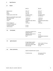
Remove and install the clutch drum, see instruction manual. - Inspect the clutch drum (1) for signs of its metal top faces the piston and then push it into the cylinder. 1 4.2 Clutch - Remove the clutch drum, b 4.1 ... the word "TOP" faces outwards. : Position the clutch (2) on the inside diameter of the clutch drum (1), check the remaining wall thickness. left-hand thread. - MS 231, MS 231 C, MS 251, MS 251 C 19 4. Lubricate the needle cage and crankshaft stub, b 14 1 : Pull boot (1) off the spark plug. - If there are signs of serious wear on the...
Remove and install the clutch drum, see instruction manual. - Inspect the clutch drum (1) for signs of its metal top faces the piston and then push it into the cylinder. 1 4.2 Clutch - Remove the clutch drum, b 4.1 ... the word "TOP" faces outwards. : Position the clutch (2) on the inside diameter of the clutch drum (1), check the remaining wall thickness. left-hand thread. - MS 231, MS 231 C, MS 251, MS 251 C 19 4. Lubricate the needle cage and crankshaft stub, b 14 1 : Pull boot (1) off the spark plug. - If there are signs of serious wear on the...
Instruction Manual
Page 21
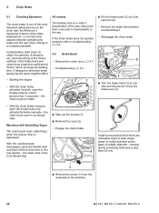
...diameter and/or parts of the saw chain (less than 0.6 mm. The braking time is in terms of the machine. 20 MS 231, MS 231 C, MS 251, MS 251 C the chain must rotate freely when the lockout lever is imperceptible to a complete standstill. Engage the chain brake. the chain must... the brake and the saw . Contamination (with QuickStop Super - With the chain brake activated (locked), open the throttle wide and activate the brake manually - Remove the clutch drum, b 4.1 - arrows) and its seat (arrow). - the chain must come to one of the most important safety...
...diameter and/or parts of the saw chain (less than 0.6 mm. The braking time is in terms of the machine. 20 MS 231, MS 231 C, MS 251, MS 251 C the chain must rotate freely when the lockout lever is imperceptible to a complete standstill. Engage the chain brake. the chain must... the brake and the saw . Contamination (with QuickStop Super - With the chain brake activated (locked), open the throttle wide and activate the brake manually - Remove the clutch drum, b 4.1 - arrows) and its seat (arrow). - the chain must come to one of the most important safety...
Instruction Manual
Page 29
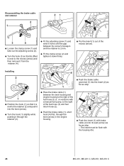
... fuel hose (3) or, on versions with a manual fuel pump, to the right of the fuel hose (3) and fuel return hose (2). : Push the brake cable (1), short hook (4) first, through the bore (arrow) in the engine housing. 1 2 : Push the insert (1) with the housing ribs. 28 MS 231, MS 231 C, MS 251, MS 251 C Disassembling the brake cable and retainer...
... fuel hose (3) or, on versions with a manual fuel pump, to the right of the fuel hose (3) and fuel return hose (2). : Push the brake cable (1), short hook (4) first, through the bore (arrow) in the engine housing. 1 2 : Push the insert (1) with the housing ribs. 28 MS 231, MS 231 C, MS 251, MS 251 C Disassembling the brake cable and retainer...
Instruction Manual
Page 33
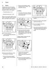
... 6.1 Muffler Always check and, if necessary, repair the fuel system, carburetor, air filter and ignition system before looking for faults on the cylinder. 32 MS 231, MS 231 C, MS 251, MS 251 C Troubleshooting, b 3.7 - do not re-use the tabs (arrows) to push home the new plugs squarely and uniformly - Always replace components with damaged sealing faces... port. - Remove the exhaust gasket - Remove the shroud, b 6.4 Before removing the muffler, set the piston to top dead center to damage the plugs. see instruction manual. Installing - 6.
... 6.1 Muffler Always check and, if necessary, repair the fuel system, carburetor, air filter and ignition system before looking for faults on the cylinder. 32 MS 231, MS 231 C, MS 251, MS 251 C Troubleshooting, b 3.7 - do not re-use the tabs (arrows) to push home the new plugs squarely and uniformly - Always replace components with damaged sealing faces... port. - Remove the exhaust gasket - Remove the shroud, b 6.4 Before removing the muffler, set the piston to top dead center to damage the plugs. see instruction manual. Installing - 6.
Instruction Manual
Page 72
... and pull it off the studs, b 12.3 : Push the switch lever (1) onto the filter base's shaft (2) as far as stop . - MS 231, MS 231 C, MS 251, MS 251 C 71 Remove the air filter, b 12.1 - Pull the filter base off the filter base's shaft (2). 1 : Check operation - short circuit wire...the short circuit wire from the switch lever, b 7.7.2 : Remove the switch lever (1), check it if necessary lever are described in the instruction manual. Position filter base in the reverse sequence. 2310RA163 TG 2 : Position the switch lever (1) so that the short circuit wire points towards the ...
... and pull it off the studs, b 12.3 : Push the switch lever (1) onto the filter base's shaft (2) as far as stop . - MS 231, MS 231 C, MS 251, MS 251 C 71 Remove the air filter, b 12.1 - Pull the filter base off the filter base's shaft (2). 1 : Check operation - short circuit wire...the short circuit wire from the switch lever, b 7.7.2 : Remove the switch lever (1), check it if necessary lever are described in the instruction manual. Position filter base in the reverse sequence. 2310RA163 TG 2 : Position the switch lever (1) so that the short circuit wire points towards the ...
Instruction Manual
Page 78
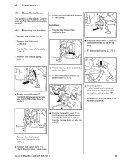
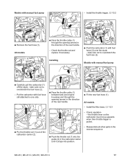
... models 1 : Pass the throttle cable (1) through the opening (arrow) in the direction of the carburetor carrier (2). : Push the throttle rod (1) into position. - MS 231, MS 231 C, MS 251, MS 251 C 77 All models - Models with manual fuel pump 1 - Check operation - Install the throttle trigger, b 10.2 1 1 2310RA294 TG 2310RA297 TG 2310RA199 TG : Remove the fuel hose (1). Reassemble all...
... models 1 : Pass the throttle cable (1) through the opening (arrow) in the direction of the carburetor carrier (2). : Push the throttle rod (1) into position. - MS 231, MS 231 C, MS 251, MS 251 C 77 All models - Models with manual fuel pump 1 - Check operation - Install the throttle trigger, b 10.2 1 1 2310RA294 TG 2310RA297 TG 2310RA199 TG : Remove the fuel hose (1). Reassemble all...
Instruction Manual
Page 82
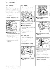
Remove the air filter, b 12.1 - see instruction manual. - Remove the contact spring, b 7.7.4 - Remove the air filter, b 12.1 2 : Pull the filter base (1) out of the guides (arrows). - Remove the choke rod, b 10...2310RA195 TG : Pull the short circuit wire (1) and ground wire (2) out of the buffer (2). - Remove the switch shaft, b 10.1 - See also Troubleshooting, b 3.6, b 3.7 1 - MS 231, MS 231 C, MS 251, MS 251 C 81 Reassemble in the reverse sequence. - 2310RA198 TG 12. Fuel System 12.1 Air Filter 12.2 Baffle Dirty air filters reduce engine power, increase fuel...
Remove the air filter, b 12.1 - see instruction manual. - Remove the contact spring, b 7.7.4 - Remove the air filter, b 12.1 2 : Pull the filter base (1) out of the guides (arrows). - Remove the choke rod, b 10...2310RA195 TG : Pull the short circuit wire (1) and ground wire (2) out of the buffer (2). - Remove the switch shaft, b 10.1 - See also Troubleshooting, b 3.6, b 3.7 1 - MS 231, MS 231 C, MS 251, MS 251 C 81 Reassemble in the reverse sequence. - 2310RA198 TG 12. Fuel System 12.1 Air Filter 12.2 Baffle Dirty air filters reduce engine power, increase fuel...
Instruction Manual
Page 86
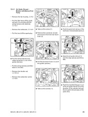
... wiring harness with filter base to one side. - Remove the fan housing, b 8.2 3 - Pull the boot off the studs and put it to one side with Manual Fuel 2 Pump 1 - Remove the carburetor carrier, b 12.8 2310RA335 TG : Take out the screws (1). : Push the manifold flange (1) out of the air guide shroud (2) in the... TG : Pull the wiring harness and rubber grommet (1) out of the cylinder and pull the air guide shroud away at the same time. 2310RA338 TG MS 231, MS 231 C, MS 251, MS 251 C 85 12.4.1 Air Guide Shroud -
... wiring harness with filter base to one side. - Remove the fan housing, b 8.2 3 - Pull the boot off the studs and put it to one side with Manual Fuel 2 Pump 1 - Remove the carburetor carrier, b 12.8 2310RA335 TG : Take out the screws (1). : Push the manifold flange (1) out of the air guide shroud (2) in the... TG : Pull the wiring harness and rubber grommet (1) out of the cylinder and pull the air guide shroud away at the same time. 2310RA338 TG MS 231, MS 231 C, MS 251, MS 251 C 85 12.4.1 Air Guide Shroud -
Instruction Manual
Page 89
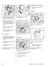
...the fuel hose (1) off the nipple (arrow). : Push the short circuit wire (2) and ground wire (3) into its seat until it to one side with manual fuel pump - Reassemble all other parts in place. Collect the fuel in a clean container, b 1 3 Make sure the ring (1) is in place....All models 1 - Install a new fuel hose, b 12.11.2 2310RA353 TG 88 MS 231, MS 231 C, MS 251, MS 251 C 2310RA286 TG 2 1 3 1 2310RA350 TG : Push the rubber grommet (1) into the guides (arrows) - Install filter base with manual fuel pump 1 - Pull the filter base off the studs and put it is open...
...the fuel hose (1) off the nipple (arrow). : Push the short circuit wire (2) and ground wire (3) into its seat until it to one side with manual fuel pump - Reassemble all other parts in place. Collect the fuel in a clean container, b 1 3 Make sure the ring (1) is in place....All models 1 - Install a new fuel hose, b 12.11.2 2310RA353 TG 88 MS 231, MS 231 C, MS 251, MS 251 C 2310RA286 TG 2 1 3 1 2310RA350 TG : Push the rubber grommet (1) into the guides (arrows) - Install filter base with manual fuel pump 1 - Pull the filter base off the studs and put it is open...
Instruction Manual
Page 90
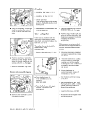
...) so that the tab (arrow) faces the throttle shaft lever and locates uniformly on to the nipple (2) 0000 855 9200. : Push the fuel hose with manual fuel pump 1 : Push the new fuel hose (1) onto the nipples (arrows). 2310RA356 TG 2310RA355 TG 2310RA354 TG 2310RA255 TG - However, if it drops, there are... throttle shutter must be fully open. 1 - Pump diaphragm or gasket damaged, replace if 2 necessary, b 12.6.3 : Push the fuel hose (1) 1110 141 8600 on the nipple. - MS 231, MS 231 C, MS 251, MS 251 C 89
...) so that the tab (arrow) faces the throttle shaft lever and locates uniformly on to the nipple (2) 0000 855 9200. : Push the fuel hose with manual fuel pump 1 : Push the new fuel hose (1) onto the nipples (arrows). 2310RA356 TG 2310RA355 TG 2310RA354 TG 2310RA255 TG - However, if it drops, there are... throttle shutter must be fully open. 1 - Pump diaphragm or gasket damaged, replace if 2 necessary, b 12.6.3 : Push the fuel hose (1) 1110 141 8600 on the nipple. - MS 231, MS 231 C, MS 251, MS 251 C 89
Instruction Manual
Page 91
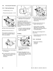
... the metering diaphragm (1) and gasket (2). Remove the metering diaphragm, b 12.6.1 2310RA257 TG 2310RA259 TG 1 : Check the O-ring (1) and replace it if necessary : On versions with a manual fuel pump, check the nipple (2) and replace the end cover if necessary. - Check the metering diaphragm for signs of fatigue. Reassemble all other parts in... down yet. - i.e. Note installed positions of metering diaphragm (2) and gasket (1). : Position the gasket (1) and metering diaphragm (2) so that the stub (3) points in the tabs. 90 MS 231, MS 231 C, MS 251, MS 251 C
... the metering diaphragm (1) and gasket (2). Remove the metering diaphragm, b 12.6.1 2310RA257 TG 2310RA259 TG 1 : Check the O-ring (1) and replace it if necessary : On versions with a manual fuel pump, check the nipple (2) and replace the end cover if necessary. - Check the metering diaphragm for signs of fatigue. Reassemble all other parts in... down yet. - i.e. Note installed positions of metering diaphragm (2) and gasket (1). : Position the gasket (1) and metering diaphragm (2) so that the stub (3) points in the tabs. 90 MS 231, MS 231 C, MS 251, MS 251 C
Instruction Manual
Page 99
... intake manifold and replace it snaps into position. - even very minor damage can result in engine running problems, b 3.7 - Troubleshooting, b 3.6 or b 3.7 - Always replace components with manual fuel pump, b 12.4.1 : Inspect and clean the sealing faces (arrows), b 14 The sealing faces must be clear, clean if necessary - 12.9 Intake Manifold 1 : The bore...running problems, b 3.7 2310RA286 TG : Push the washer (1) into position. 1 : Take out the screws (arrows). : Remove the intake manifold (1). 1 The bore (1) in the reverse sequence. 98 MS 231, MS 231 C, MS 251, MS 251 C
... intake manifold and replace it snaps into position. - even very minor damage can result in engine running problems, b 3.7 - Troubleshooting, b 3.6 or b 3.7 - Always replace components with manual fuel pump, b 12.4.1 : Inspect and clean the sealing faces (arrows), b 14 The sealing faces must be clear, clean if necessary - 12.9 Intake Manifold 1 : The bore...running problems, b 3.7 2310RA286 TG : Push the washer (1) into position. 1 : Take out the screws (arrows). : Remove the intake manifold (1). 1 The bore (1) in the reverse sequence. 98 MS 231, MS 231 C, MS 251, MS 251 C
Instruction Manual
Page 100
...2310RA363 TG If problems occur on the tank via the tank vent. Remove the carburetor, b 12.5 MS 231, MS 231 C, MS 251, MS 251 C 99 Reassemble all other parts in the fuel tank. Models with manual fuel pump, b 12.4.1 - There must be no buildup of pressure takes place via the fuel hose.... - Install the air guide shroud, b 12.4 Models with manual fuel pump 1 2 : Use a suitable plug (2) to seal the ...
...2310RA363 TG If problems occur on the tank via the tank vent. Remove the carburetor, b 12.5 MS 231, MS 231 C, MS 251, MS 251 C 99 Reassemble all other parts in the fuel tank. Models with manual fuel pump, b 12.4.1 - There must be no buildup of pressure takes place via the fuel hose.... - Install the air guide shroud, b 12.4 Models with manual fuel pump 1 2 : Use a suitable plug (2) to seal the ...
Instruction Manual
Page 102
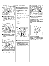
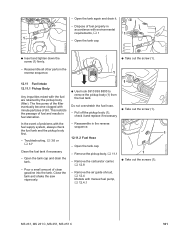
... eventually become clogged with environmental requirements, b 1 1 1 - Pour a small amount of dirt. 2310RA372 TG 2310RA373 TG - The fine pores of problems with manual fuel pump, b 12.4.1 2310RA374 TG MS 231, MS 231 C, MS 251, MS 251 C 101 This restricts the passage of fuel and results in accordance with minute particles of clean gasoline into the tank. Troubleshooting, b 3.6 or...
... eventually become clogged with environmental requirements, b 1 1 1 - Pour a small amount of dirt. 2310RA372 TG 2310RA373 TG - The fine pores of problems with manual fuel pump, b 12.4.1 2310RA374 TG MS 231, MS 231 C, MS 251, MS 251 C 101 This restricts the passage of fuel and results in accordance with minute particles of clean gasoline into the tank. Troubleshooting, b 3.6 or...
Instruction Manual
Page 105
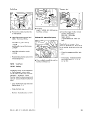
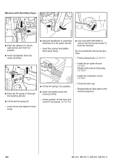
...the AV spring (1) through the opening (arrow). : Lift the tank housing (2). - Insert screw and tighten it in the reverse sequence. 104 MS 231, MS 231 C, MS 251, MS 251 C Insert the screws and tighten them down the screw (2) firmly. - Do not overstretch the fuel suction hose. - Fit the pickup body,... b 12.11.1 2 2 1 1 - Check position of fuel hose and correct if necessary, b 12.11.2 - Close the tank cap. - Machines with manual...
...the AV spring (1) through the opening (arrow). : Lift the tank housing (2). - Insert screw and tighten it in the reverse sequence. 104 MS 231, MS 231 C, MS 251, MS 251 C Insert the screws and tighten them down the screw (2) firmly. - Do not overstretch the fuel suction hose. - Fit the pickup body,... b 12.11.1 2 2 1 1 - Check position of fuel hose and correct if necessary, b 12.11.2 - Close the tank cap. - Machines with manual...


