
Instruction Manual
Page 2
... has been made to Using this Manual 2 Safety Precautions 3 Applications 4 Assembling the Sharpener 4 Mounting the Grinding Wheel 6 Test Run 7 Mounting the Swivelling Tool Rest .... 7 Chains with 1.3 mm (0.05") Drive Link Gauge 8 Preparations for choosing a quality engineered STIHL product. Please contact your machine. F4. BA_SE_016_002_01_04.fm Contents Guide to ensure your satisfaction and troublefree use of Conformity 21 Quality Certification 22 STIHl HOS English Dear Customer...
... has been made to Using this Manual 2 Safety Precautions 3 Applications 4 Assembling the Sharpener 4 Mounting the Grinding Wheel 6 Test Run 7 Mounting the Swivelling Tool Rest .... 7 Chains with 1.3 mm (0.05") Drive Link Gauge 8 Preparations for choosing a quality engineered STIHL product. Please contact your machine. F4. BA_SE_016_002_01_04.fm Contents Guide to ensure your satisfaction and troublefree use of Conformity 21 Quality Certification 22 STIHl HOS English Dear Customer...
Instruction Manual
Page 3
... in the manual may not be covered in this manual. Therefore some changes, modifications and improvements may be available as special accessories from time to time. If the operating characteristics or the appearance of an accident or personal injury or serious damage to property. Such paragraphs are supported by illustrations. English Guide to Using this Manual Pictograms All the pictograms attached to...
... in the manual may not be covered in this manual. Therefore some changes, modifications and improvements may be available as special accessories from time to time. If the operating characteristics or the appearance of an accident or personal injury or serious damage to property. Such paragraphs are supported by illustrations. English Guide to Using this Manual Pictograms All the pictograms attached to...
Instruction Manual
Page 4
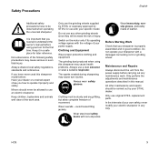
... use original STIHL replacement parts. All other grinding wheels since they will increase the risk of injury. It is properly assembled and in any maintenance work area. Minors should be allowed to use with the voltage of your sharpener with non-slip soles. Wear steel-toed safety boots with a damaged connecting cord or grinding wheel. Switch on the motor only if its operating...
... use original STIHL replacement parts. All other grinding wheels since they will increase the risk of injury. It is properly assembled and in any maintenance work area. Minors should be allowed to use with the voltage of your sharpener with non-slip soles. Wear steel-toed safety boots with a damaged connecting cord or grinding wheel. Switch on the motor only if its operating...
Instruction Manual
Page 5
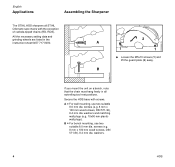
..., use two suitable 8.0 mm dia. A 1 2 1 : Loosen the M5x10 screws (1) and lift the guard plate (2) away. screws (e.g. 8 mm x 100 mm wood screws, DIN 571-St), 8.4 mm dia. washers. 4 HOS 523BA045 KN 523BA046 KN English Applications Assembling the Sharpener The STIHL HOS sharpens all swivelling tool rest positions. B If you mount the unit on a bench, note that the chain must hang freely in the instruction...
..., use two suitable 8.0 mm dia. A 1 2 1 : Loosen the M5x10 screws (1) and lift the guard plate (2) away. screws (e.g. 8 mm x 100 mm wood screws, DIN 571-St), 8.4 mm dia. washers. 4 HOS 523BA045 KN 523BA046 KN English Applications Assembling the Sharpener The STIHL HOS sharpens all swivelling tool rest positions. B If you mount the unit on a bench, note that the chain must hang freely in the instruction...
Instruction Manual
Page 7
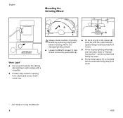
... skin and clean up the edges with a round file. : Position lamp socket in the spacer (4). English Mounting the Grinding Wheel 523BA051 KN 523BA046 KN 523BA052 KN 2 1 1 5 4 3 6 7 Work Light* : Use a punch to Using this Manual" 6 HOS with its raised side facing away from motor). : Fit the required grinding wheel (6) - Never use damaged grinding wheels. : Loosen the M5x10 screws (1), then lift and remove the guard plate (2). : Fit...
... skin and clean up the edges with a round file. : Position lamp socket in the spacer (4). English Mounting the Grinding Wheel 523BA051 KN 523BA046 KN 523BA052 KN 2 1 1 5 4 3 6 7 Work Light* : Use a punch to Using this Manual" 6 HOS with its raised side facing away from motor). : Fit the required grinding wheel (6) - Never use damaged grinding wheels. : Loosen the M5x10 screws (1), then lift and remove the guard plate (2). : Fit...
Instruction Manual
Page 8
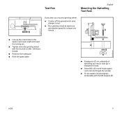
... sharpener's base. : Insert M8 x 60 round head square neck bolt (3) through the slot (4). : Fit the washer (5) and tighten moderately with the knurled nut (8) - left-hand thread. : Remove the locking pin. : Refit the guard plate. 1 4 2 5 6 : Engage pin (1) on underside of swivelling tool rest in hole (2) in the spacer and motor shaft and insert the locking pin. : Tighten down the grinding wheel with the M8 wingnut (6).
... sharpener's base. : Insert M8 x 60 round head square neck bolt (3) through the slot (4). : Fit the washer (5) and tighten moderately with the knurled nut (8) - left-hand thread. : Remove the locking pin. : Refit the guard plate. 1 4 2 5 6 : Engage pin (1) on underside of swivelling tool rest in hole (2) in the spacer and motor shaft and insert the locking pin. : Tighten down the grinding wheel with the M8 wingnut (6).

Instruction Manual
Page 9
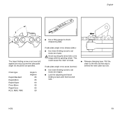
English Chains with 1.3 mm (0.05") Drive Link Gauge 1 1 1 2 1 2 3 5 4 5 4 7 8 6 522BA001 KN 522BA002 KN 522BA003 KN : Unscrew the clamping lever and remove it together with the thrust pad. : Remove the two M6x8 pan head screws (1) from the swivelling tool rest. : Remove the two M6x8 pan head screws (2) from the guide rail. 2 2 : Position 0.15 mm (0.006") shim (3) for chain with 1.3 mm (0.05") drive links between the guide rail and swivelling tool rest...
English Chains with 1.3 mm (0.05") Drive Link Gauge 1 1 1 2 1 2 3 5 4 5 4 7 8 6 522BA001 KN 522BA002 KN 522BA003 KN : Unscrew the clamping lever and remove it together with the thrust pad. : Remove the two M6x8 pan head screws (1) from the swivelling tool rest. : Remove the two M6x8 pan head screws (2) from the guide rail. 2 2 : Position 0.15 mm (0.006") shim (3) for chain with 1.3 mm (0.05") drive links between the guide rail and swivelling tool rest...

Instruction Manual
Page 10
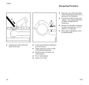
HOS 9 cutting edges must point to the shape and size of the other cutters. : Find the shortest cutter (master cutter). : Release clamping lever (1). : Place the chain, drive link tangs (2) downward, in the clamping rail (3) - Grind the new cutters back to the left. : Pull the master cutter back against the stop (4). Preparations for Sharpening English 523BA012 KN 523BA061 KN 523BA062 KN 4 2 3 1 Do not switch on the motor yet. : Replace cutters with severely worn or damaged cutting edges.
HOS 9 cutting edges must point to the shape and size of the other cutters. : Find the shortest cutter (master cutter). : Release clamping lever (1). : Place the chain, drive link tangs (2) downward, in the clamping rail (3) - Grind the new cutters back to the left. : Pull the master cutter back against the stop (4). Preparations for Sharpening English 523BA012 KN 523BA061 KN 523BA062 KN 4 2 3 1 Do not switch on the motor yet. : Replace cutters with severely worn or damaged cutting edges.

Instruction Manual
Page 11
Lateral Adjustment : Back off the travel limiting screw (8). : Use the handle to bring the grinding wheel down to the specified sharpening angle (see separate data sheet). : Tighten down the wingnut (7). English 55 45 5 6 35 25 1510 - 0 + 1015 25 35 8 45 55 522BA004 KN 522BA011 KN 522BA005 KN 523BA063 KN 7 The stop's pivot pin (5) moves backward and forward in the arm. : To sharpen the left-hand row of cutters: Pull the stop in the direction of arrow. : Set the scale (6) on the swivelling tool rest to the chain. 10 HOS
Lateral Adjustment : Back off the travel limiting screw (8). : Use the handle to bring the grinding wheel down to the specified sharpening angle (see separate data sheet). : Tighten down the wingnut (7). English 55 45 5 6 35 25 1510 - 0 + 1015 25 35 8 45 55 522BA004 KN 522BA011 KN 522BA005 KN 523BA063 KN 7 The stop's pivot pin (5) moves backward and forward in the arm. : To sharpen the left-hand row of cutters: Pull the stop in the direction of arrow. : Set the scale (6) on the swivelling tool rest to the chain. 10 HOS

Instruction Manual
Page 12
Initial Adjustment of Grinding Depth : Use the handle (10) to move the motor arm down until the HOS 11 4 9 English 10 522BA006 KN 523BA066 KN 522BA007 KN : Move the stop (4) with the adjusting screw (9) so that the master cutter's side plate locates against the grinding wheel. : Clamp the chain in position. : Lock the adjusting screw in position with the knurled nut.
Initial Adjustment of Grinding Depth : Use the handle (10) to move the motor arm down until the HOS 11 4 9 English 10 522BA006 KN 523BA066 KN 522BA007 KN : Move the stop (4) with the adjusting screw (9) so that the master cutter's side plate locates against the grinding wheel. : Clamp the chain in position. : Lock the adjusting screw in position with the knurled nut.
Instruction Manual
Page 13
... applying the wheel several times - Do not remove too much material. : If necessary, switch off motor and readjust - see "Lateral Adjustment" in a single pass. : When result is satisfactory, check the grinding depth. 522BA008 KN 522BA009 KN : grinding wheel (11) touches the gullet of the cutter. : Screw travel limiting screw (8) down as far as stop lug. : Tighten down the knurled nut (12...
... applying the wheel several times - Do not remove too much material. : If necessary, switch off motor and readjust - see "Lateral Adjustment" in a single pass. : When result is satisfactory, check the grinding depth. 522BA008 KN 522BA009 KN : grinding wheel (11) touches the gullet of the cutter. : Screw travel limiting screw (8) down as far as stop lug. : Tighten down the knurled nut (12...
Instruction Manual
Page 14
... set motor arm lower. The travel limiting screws with the grinding wheel. Avoid touching the drive links or tie straps with their knurled nuts. : Release clamping lever. This could cause the chain to check sharpening data. English 523BA022 KN 523BA070 KN 523BA071 KN 1 : Use a filing gauge to break. If side plate angle is too acute (narrow): : Use travel limiting screw to set motor arm higher. : Lock the adjusting...
... set motor arm lower. The travel limiting screws with the grinding wheel. Avoid touching the drive links or tie straps with their knurled nuts. : Release clamping lever. This could cause the chain to check sharpening data. English 523BA022 KN 523BA070 KN 523BA071 KN 1 : Use a filing gauge to break. If side plate angle is too acute (narrow): : Use travel limiting screw to set motor arm higher. : Lock the adjusting...
Instruction Manual
Page 15
... M8 wingnut firmly. 14 HOS Setting the Scale 35 25 1510 - 0 + 1015 25 35 1 45 55 522BA010 KN : Set the scale (1) on the swivelling tool rest to be lowered. Checking Depth Gauge Setting : Select the filing gauge (special accessory) that of the other side of the chain. : Move the stop's pivot pin so that the stop lines up with the second row...
... M8 wingnut firmly. 14 HOS Setting the Scale 35 25 1510 - 0 + 1015 25 35 1 45 55 522BA010 KN : Set the scale (1) on the swivelling tool rest to be lowered. Checking Depth Gauge Setting : Select the filing gauge (special accessory) that of the other side of the chain. : Move the stop's pivot pin so that the stop lines up with the second row...

Instruction Manual
Page 16
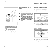
... until the grinding wheel touches the depth gauge. : Screw home the travel limiting screw (1) until the back of the grinding wheel is centered above the depth gauge. : Clamp the chain in position. : Turn the adjusting screw (2) until it butts against the stop lug (2). : Put on safety glasses. : Switch on the motor. : Carefully bring the motor arm down . : Slide the chain along the guide rail until the...
... until the grinding wheel touches the depth gauge. : Screw home the travel limiting screw (1) until the back of the grinding wheel is centered above the depth gauge. : Clamp the chain in position. : Turn the adjusting screw (2) until it butts against the stop lug (2). : Put on safety glasses. : Switch on the motor. : Carefully bring the motor arm down . : Slide the chain along the guide rail until the...

Instruction Manual
Page 17
... English Dressing the Grinding Wheel 3 4 5 : Switch off the motor. : Place the filing gauge (5) on the chain. : If the depth gauge (4) still projects above the filing gauge, make appropriate adjustment with the travel limiting screw (1). : Remove the filing gauge (5). : Switch on the motor. : Carefully bring the motor arm down. : Switch off the motor. : Use dressing gauge (special accessory) to check the profile of the grinding wheel. : Set scale C on swivelling tool rest to "0". : Use dressing stone (special...
... English Dressing the Grinding Wheel 3 4 5 : Switch off the motor. : Place the filing gauge (5) on the chain. : If the depth gauge (4) still projects above the filing gauge, make appropriate adjustment with the travel limiting screw (1). : Remove the filing gauge (5). : Switch on the motor. : Carefully bring the motor arm down. : Switch off the motor. : Use dressing gauge (special accessory) to check the profile of the grinding wheel. : Set scale C on swivelling tool rest to "0". : Use dressing stone (special...

Instruction Manual
Page 18
...Machine mounting Switch Power supply cord Grinding wheel Cooling air inlets Accessible screws and nuts Shield Clamp and guide rail Stop and lock 1) Have work performed by qualified electrician Visual inspection condition) Clean Check Retighten Check operation Replace 1) Check Replace 1) Check (wear) Check profile Dress Replace Clean Retighten Check Replace Check Replace Check Replace X X X X X X X X X X X X before starting work after finishing work or daily weekly monthly if problem if damaged as required English X X X X X X X X X X X X X HOS 17 If your daily working time is...
...Machine mounting Switch Power supply cord Grinding wheel Cooling air inlets Accessible screws and nuts Shield Clamp and guide rail Stop and lock 1) Have work performed by qualified electrician Visual inspection condition) Clean Check Retighten Check operation Replace 1) Check Replace 1) Check (wear) Check profile Dress Replace Clean Retighten Check Replace Check Replace Check Replace X X X X X X X X X X X X before starting work after finishing work or daily weekly monthly if problem if damaged as required English X X X X X X X X X X X X X HOS 17 If your daily working time is...
Instruction Manual
Page 19
Using attachments or sharpening tools not approved by continuing to be performed by non-observance of the safety precautions, operating and maintenance instructions in this manual helps reduce the risk of parts other parts, this includes: - If these maintenance operations cannot be performed by the owner, they should be replaced in this owner's manual. Among other than original STIHL replacement parts. - Clamping lever and thrust pad - Clamping and guide rails - Maintenance Work...
Using attachments or sharpening tools not approved by continuing to be performed by non-observance of the safety precautions, operating and maintenance instructions in this manual helps reduce the risk of parts other parts, this includes: - If these maintenance operations cannot be performed by the owner, they should be replaced in this owner's manual. Among other than original STIHL replacement parts. - Clamping lever and thrust pad - Clamping and guide rails - Maintenance Work...

Instruction Manual
Page 20
Main Parts of Sharpener 7 4 11 2 1 10 8 65 3 Specifications English Motor Type: Single-phase AC, squirrel-cage motor Operating voltage: 230 V Frequency: 50 Hz Rated current: 1.3 A Power rating: 0.18 kW Motor speed: 2,800 RPM Type of protection: IP 54 (DIN 40050) Equivalent sound power level 1) Lpeq 75 dB (A) 9 522BA000 KN 1 Motor 2 Switch box 3 Swivelling tool rest 4 Motor arm 5 Clamping lever 6 Thrust pad HOS 7 Travel limiting screw 8 Stop 9 Adjusting screw 10 Grinding wheel 11 Stop lug 1) according to EN ISO 11204, measured at user's ear while sharpening a saw chain 19
Main Parts of Sharpener 7 4 11 2 1 10 8 65 3 Specifications English Motor Type: Single-phase AC, squirrel-cage motor Operating voltage: 230 V Frequency: 50 Hz Rated current: 1.3 A Power rating: 0.18 kW Motor speed: 2,800 RPM Type of protection: IP 54 (DIN 40050) Equivalent sound power level 1) Lpeq 75 dB (A) 9 522BA000 KN 1 Motor 2 Switch box 3 Swivelling tool rest 4 Motor arm 5 Clamping lever 6 Thrust pad HOS 7 Travel limiting screw 8 Stop 9 Adjusting screw 10 Grinding wheel 11 Stop lug 1) according to EN ISO 11204, measured at user's ear while sharpening a saw chain 19
Instruction Manual
Page 21
Other repair work may appear alone on small parts. 20 HOS The symbol may be performed only by an authorized STIHL dealer. English Special Accessories Work light Dressing gauge Dressing stone Maintenance and Repairs The user of this unit should carry out only the maintenance operations described in this manual. Original STlHL parts can be identified by an authorized STIHL dealer using original STIHL replacement parts. Warranty claims following repairs can be accepted only if the repair has been performed by the STIHL part number, the STIHl logo and the STlHL parts symbol (.
Other repair work may appear alone on small parts. 20 HOS The symbol may be performed only by an authorized STIHL dealer. English Special Accessories Work light Dressing gauge Dressing stone Maintenance and Repairs The user of this unit should carry out only the maintenance operations described in this manual. Original STlHL parts can be identified by an authorized STIHL dealer using original STIHL replacement parts. Warranty claims following repairs can be accepted only if the repair has been performed by the STIHL part number, the STIHl logo and the STlHL parts symbol (.
Instruction Manual
Page 22
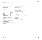
...-1 Steinhauser Director Group Product Management Engineering Services English HOS 21 KG conforms to the specifications of Conformity Andreas Stihl AG & Co. Certificate of Directives 73/23/EEC, 98/37/EC and 89/336/EEC. KG Badstr. 115 71336 Waiblingen certify that the new machine described below Category: Make: Model: Serial identification: Universal sharpener STIHL HOS 5202 Technical documents deposited at...
...-1 Steinhauser Director Group Product Management Engineering Services English HOS 21 KG conforms to the specifications of Conformity Andreas Stihl AG & Co. Certificate of Directives 73/23/EEC, 98/37/EC and 89/336/EEC. KG Badstr. 115 71336 Waiblingen certify that the new machine described below Category: Make: Model: Serial identification: Universal sharpener STIHL HOS 5202 Technical documents deposited at...


