Users Guide
Page 3
... settings • DME channel 5 to setup Classification NS-Bus Functions supported Menu No. The related button operation and menu settings are as follows. XKS-C8111/ XKS-C9111/ XKS-C9121/ XKS-C8166 720P format page 443 page 454 Format converter XVS-9000 internal format converter settings (with resource sharing enabled only) 7332.11 page 210 Re-entry signal Release of P-Bus 7355.1 compatible devices via a network TCP/IP connected 7325.4 device control...
... settings • DME channel 5 to setup Classification NS-Bus Functions supported Menu No. The related button operation and menu settings are as follows. XKS-C8111/ XKS-C9111/ XKS-C9121/ XKS-C8166 720P format page 443 page 454 Format converter XVS-9000 internal format converter settings (with resource sharing enabled only) 7332.11 page 210 Re-entry signal Release of P-Bus 7355.1 compatible devices via a network TCP/IP connected 7325.4 device control...
Users Guide
Page 15
... Setting Status of the MKS-8080/8082 in Simple Connection 534 Network AUX Remote Panel 535 Macro File Editing Rules 536 Macro File Syntax 536 Syntax of Event and Continue Statements 536 File Name 536 Saving and Loading a File 537 Errors 537 Correspondence Between Events and Symbols 537 Symbols and Parameters 539 Example of File Contents 543 Content Displayed in Macro Attachment List...
... Setting Status of the MKS-8080/8082 in Simple Connection 534 Network AUX Remote Panel 535 Macro File Editing Rules 536 Macro File Syntax 536 Syntax of Event and Continue Statements 536 File Name 536 Saving and Loading a File 537 Errors 537 Correspondence Between Events and Symbols 537 Symbols and Parameters 539 Example of File Contents 543 Content Displayed in Macro Attachment List...
Users Guide
Page 60
... the parameter value. • Turn the Z-ring to their default values, in the shortcut menu You can create a shortcut menu by the user Factory: Factory default state For details, see "Menu Tree" (page 501). For details about menu macros, see "Setting the Mouse Wheel Function when Setting Parameters" (page 438) and "Setting the Mouse Button Function when Setting Parameters" (page 438). Using a Mouse You can also...
... the parameter value. • Turn the Z-ring to their default values, in the shortcut menu You can create a shortcut menu by the user Factory: Factory default state For details, see "Menu Tree" (page 501). For details about menu macros, see "Setting the Mouse Wheel Function when Setting Parameters" (page 438) and "Setting the Mouse Button Function when Setting Parameters" (page 438). Using a Mouse You can also...
Users Guide
Page 67
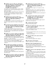
..., QSFP28 type: XKS-C8166) Reserved for future use . p MVS LAN (multi format video switcher LAN) connector (RJ-45 compliant) Connect to an Ethernet switch. 1) Used to communicate between switcher control stations connected to the XVS-9000/8000/ 7000/6000 Installation Manual. For details about Ethernet switch connection, refer to an Ethernet switch. 1) For details about supported Ethernet switches, contact your Sony service or sales representative. g OUTPUT connectors (BNC type: XKS...
..., QSFP28 type: XKS-C8166) Reserved for future use . p MVS LAN (multi format video switcher LAN) connector (RJ-45 compliant) Connect to an Ethernet switch. 1) Used to communicate between switcher control stations connected to the XVS-9000/8000/ 7000/6000 Installation Manual. For details about Ethernet switch connection, refer to an Ethernet switch. 1) For details about supported Ethernet switches, contact your Sony service or sales representative. g OUTPUT connectors (BNC type: XKS...
Users Guide
Page 123
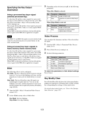
... 5 Black Level Black level To return the parameters to re-entry signals PROC V and PROC K. When [Key Blink] is selected No. Key Blink: Sets key blinking. No. Key Modify Clear Press [Default Recall] at regular intervals. Parameter Adjustment 1 Blink Rate Length of blink cycle 2 Duty Proportion of the menu display, turning it on the keyer, the key fill and key source...
... 5 Black Level Black level To return the parameters to re-entry signals PROC V and PROC K. When [Key Blink] is selected No. Key Blink: Sets key blinking. No. Key Modify Clear Press [Default Recall] at regular intervals. Parameter Adjustment 1 Blink Rate Length of blink cycle 2 Duty Proportion of the menu display, turning it on the keyer, the key fill and key source...

Users Guide
Page 170
... mode Enabling pair mode allows you to link operation of a pair of files can output audio data. • In variable-speed playback, audio data is displayed after the name. space comma), . (period • The following characters cannot be used for operation. Notes • The created folder hierarchy can also play audio data, set the signal output to monitor the data. Audio data recording cannot be displayed...
... mode Enabling pair mode allows you to link operation of a pair of files can output audio data. • In variable-speed playback, audio data is displayed after the name. space comma), . (period • The following characters cannot be used for operation. Notes • The created folder hierarchy can also play audio data, set the signal output to monitor the data. Audio data recording cannot be displayed...

Users Guide
Page 209
... switchers 1 and 2 are different and Dual Simul mode is shared between logical switchers 1 and 2. Engineering Setup >System >Network Config >IP Address menu (7311.2) - Engineering Setup >System >Network Config >Net I /F Initialize menu (7311.1) - Engineering Setup >System >Network Config >Input/ Output menu (7311.5) - Engineering Setup >System >Network Config >NMOS menu (7311.7) - All folders and files are linked on the frame memory folder mode setting. Notes • When the signal formats of the resource assignments. -
... switchers 1 and 2 are different and Dual Simul mode is shared between logical switchers 1 and 2. Engineering Setup >System >Network Config >IP Address menu (7311.2) - Engineering Setup >System >Network Config >Net I /F Initialize menu (7311.1) - Engineering Setup >System >Network Config >Input/ Output menu (7311.5) - Engineering Setup >System >Network Config >NMOS menu (7311.7) - All folders and files are linked on the frame memory folder mode setting. Notes • When the signal formats of the resource assignments. -

Users Guide
Page 210
... only). Internal format converter settings • Set the FC channels of internal format converters for use as inputs (XVS-8000/7000/6000 only) • Set logical switcher 2 signals as input signals on logical switcher 2 can be used on logical switcher 1 when resource sharing is set to dedicated mode and a shared FM output is selected, the thumbnail for files are not displayed in the Frame Memory menu of logical switcher...
... only). Internal format converter settings • Set the FC channels of internal format converters for use as inputs (XVS-8000/7000/6000 only) • Set logical switcher 2 signals as input signals on logical switcher 2 can be used on logical switcher 1 when resource sharing is set to dedicated mode and a shared FM output is selected, the thumbnail for files are not displayed in the Frame Memory menu of logical switcher...
Users Guide
Page 259
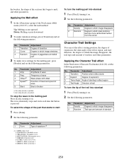
...wave alternately stops and starts each time the button is disabled. Applying the Character Trail effect In the Non Linear >Character Trail menu (4141.28), set the following parameters. the borders, the shape of the sections that starts to melt 1 Press [Form]. 2 Set the following parameters.... melting part into stardust 1 Press [Pixel], turning it on . 2 Set the following parameters. To select the shape of the Non Linear >Melt menu (4141.27), select the melt method. No. No. Parameter Adjustment 1 Amp Amplitude of wave 2 Freq Frequency of wave 3 Offset a) Wave phase shift...
...wave alternately stops and starts each time the button is disabled. Applying the Character Trail effect In the Non Linear >Character Trail menu (4141.28), set the following parameters. the borders, the shape of the sections that starts to melt 1 Press [Form]. 2 Set the following parameters.... melting part into stardust 1 Press [Pixel], turning it on . 2 Set the following parameters. To select the shape of the Non Linear >Melt menu (4141.27), select the melt method. No. No. Parameter Adjustment 1 Amp Amplitude of wave 2 Freq Frequency of wave 3 Offset a) Wave phase shift...

Users Guide
Page 334
... details, see "Setting User Regions" (page 441). 1 Press [Clip Auto Play]. The status area shows the region names, register numbers, and the lock status. 2 Press the region display in the upper part of the list, then select the region in the selection window. 3 Select a register. 4 In the group, set for 2nd DME channel. Aux Cross-point hold is set for video bus selected...
... details, see "Setting User Regions" (page 441). 1 Press [Clip Auto Play]. The status area shows the region names, register numbers, and the lock status. 2 Press the region display in the upper part of the list, then select the region in the selection window. 3 Select a register. 4 In the group, set for 2nd DME channel. Aux Cross-point hold is set for video bus selected...
Users Guide
Page 387
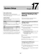
..." refers to 8) using the keyboard window, then press [Enter]. 387 Settings Relating to the Network This section describes the configuration of the Menu Panel 1 In the Engineering Setup >System >Network Config menu (7311), press [Group ID]. 2 Enter the group ID number (1 to all devices connected on the same network, the unit IDs are set as follows. Configuring the NFS Server Set the address of 2nd switcher...
..." refers to 8) using the keyboard window, then press [Enter]. 387 Settings Relating to the Network This section describes the configuration of the Menu Panel 1 In the Engineering Setup >System >Network Config menu (7311), press [Group ID]. 2 Enter the group ID number (1 to all devices connected on the same network, the unit IDs are set as follows. Configuring the NFS Server Set the address of 2nd switcher...
Users Guide
Page 390
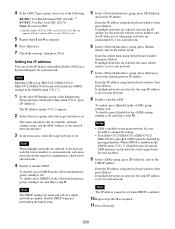
... address cannot be set when DHCP is installed, LSM cannot be disabled by 1 for each network. The unit supports 25G×4 to achieve 100G, so only CL108 is set for each network. The status area shows the slot number, network settings status, and the MAC address of the following. Enter the IP address using the keyboard window, then press [Enter]. Enter the subnet mask using the keyboard window...
... address cannot be set when DHCP is installed, LSM cannot be disabled by 1 for each network. The unit supports 25G×4 to achieve 100G, so only CL108 is set for each network. The status area shows the slot number, network settings status, and the MAC address of the following. Enter the IP address using the keyboard window, then press [Enter]. Enter the subnet mask using the keyboard window...
Users Guide
Page 397
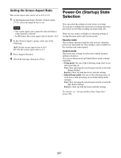
... device at startup (Resume mode and Custom mode). Resume mode This resumes operation with the factory default settings. Custom mode This mode uses settings saved in force when the power was last turned off. This setting is fixed to 16:9. 2 In the group, select one of the following states of the following setup states to use after powering on . User: Start up using the user data previously saved with [Setup Define]. For details, see...
... device at startup (Resume mode and Custom mode). Resume mode This resumes operation with the factory default settings. Custom mode This mode uses settings saved in force when the power was last turned off. This setting is fixed to 16:9. 2 In the group, select one of the following states of the following setup states to use after powering on . User: Start up using the user data previously saved with [Setup Define]. For details, see...
Users Guide
Page 403
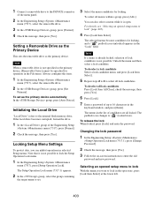
... an opened setup menu to lock With the menu you can also select a menu while it is already locked, selection of the Engineering Setup >System >Maintenance menu (7317), press [Format]. 2 Check the message, then press [Yes]. Changing the lock password 1 In the Engineering Setup >System >Maintenance >Setup Operation Lock menu (7317.1), press [Change Password]. 2 Check the message, then press [Yes]. 3 Follow the on-screen instructions to...
... an opened setup menu to lock With the menu you can also select a menu while it is already locked, selection of the Engineering Setup >System >Maintenance menu (7317), press [Format]. 2 Check the message, then press [Yes]. Changing the lock password 1 In the Engineering Setup >System >Maintenance >Setup Operation Lock menu (7317.1), press [Change Password]. 2 Check the message, then press [Yes]. 3 Follow the on-screen instructions to...
Users Guide
Page 404
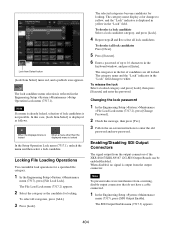
... the Engineering Setup >System >Maintenance >File Load Lock menu (7317.2), press [Change Password]. 2 Check the message, then press [Yes]. 3 Follow the on-screen instructions to white. Enabling/Disabling SDI Output Connectors The signal output from occurring, disable output connectors that do not have a cable connected. 1 In the Engineering Setup >System >Maintenance menu (7317), press [SDI Output Enable]. The category name display color changes to 16...
... the Engineering Setup >System >Maintenance >File Load Lock menu (7317.2), press [Change Password]. 2 Check the message, then press [Yes]. 3 Follow the on-screen instructions to white. Enabling/Disabling SDI Output Connectors The signal output from occurring, disable output connectors that do not have a cable connected. 1 In the Engineering Setup >System >Maintenance menu (7317), press [SDI Output Enable]. The category name display color changes to 16...
Users Guide
Page 525
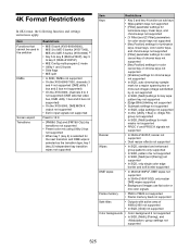
..., channels 3 and 4 not supported (DME utility 1 bus and 2 bus not supported) • On the XVS-6000, channels 2 to 4 not supported (DME external video bus, DME utility 1 bus and 2 bus not supported) • On the XVS-8000, DME MON K output not supported • Ext In input signals not supported Fixed to 16:9 • [FM5&6 Clip] and [FM7&8 Clip] clip transitions not supported • Preset color mix using...
..., channels 3 and 4 not supported (DME utility 1 bus and 2 bus not supported) • On the XVS-6000, channels 2 to 4 not supported (DME external video bus, DME utility 1 bus and 2 bus not supported) • On the XVS-8000, DME MON K output not supported • Ext In input signals not supported Fixed to 16:9 • [FM5&6 Clip] and [FM7&8 Clip] clip transitions not supported • Preset color mix using...
Users Guide
Page 526
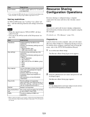
... selected. For details about computer connection and accessing the menu, refer to the ICP-X7000 Installation Manual. 526 Note For the administrator user name and password, refer to the ICP-X7000 Installation Manual. 1 Access Resource Share Setup. Resource Sharing Configuration Operations Resource sharing is configured using a computer connected to [Key3 + Key PVW]. Preparations Launch a browser on the XVS-9000/ 7000/6000) Priority settings not supported (Key 4 and key 3 are fixed at the top, in...
... selected. For details about computer connection and accessing the menu, refer to the ICP-X7000 Installation Manual. 526 Note For the administrator user name and password, refer to the ICP-X7000 Installation Manual. 1 Access Resource Share Setup. Resource Sharing Configuration Operations Resource sharing is configured using a computer connected to [Key3 + Key PVW]. Preparations Launch a browser on the XVS-9000/ 7000/6000) Priority settings not supported (Key 4 and key 3 are fixed at the top, in...
Users Guide
Page 529
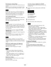
... assigned to display the pop-up window. To restore resource assignments to defaults Click/tap [Default Recall], check the message, then click/tap [Yes]. 5 Set the frame memory folder mode in a separate window. Note If logical switcher 1 or 2 is displayed in [FM Folder Mode]. In addition, the color backgrounds that can be used on logical switchers 1 and 2. Multi viewer output settings (XVS-9000 only) Click...
... assigned to display the pop-up window. To restore resource assignments to defaults Click/tap [Default Recall], check the message, then click/tap [Yes]. 5 Set the frame memory folder mode in a separate window. Note If logical switcher 1 or 2 is displayed in [FM Folder Mode]. In addition, the color backgrounds that can be used on logical switchers 1 and 2. Multi viewer output settings (XVS-9000 only) Click...

Users Guide
Page 535
Set to "Local" (Color Settings on the Display Settings page) Select from a remote panel on the network. For details, see "Remote Panel Connection Status" (page 493). 535 In a simple connection, the MKS-R3210/R1620 Remote Control Panel and switcher are required in order to the ICP-X7000 Installation Manual. For details about setup, refer to a remote panel. Switcher settings To use with a switcher, and uses the MKS-R3210/ R1620 Remote Control Panel...
Set to "Local" (Color Settings on the Display Settings page) Select from a remote panel on the network. For details, see "Remote Panel Connection Status" (page 493). 535 In a simple connection, the MKS-R3210/R1620 Remote Control Panel and switcher are required in order to the ICP-X7000 Installation Manual. For details about setup, refer to a remote panel. Switcher settings To use with a switcher, and uses the MKS-R3210/ R1620 Remote Control Panel...
Users Guide
Page 563
... 143, 150 Mouse operation 60 setting 438 Multi program 2 199 Multi-program mode 439 Multi viewer 463 N NAM 84 Network interface 388 NFS 376, 387 setting 387 Network AUX remote panel 535 Network interface Initialize 388 protocol 392 service port 388 setting 388 Network port external devices 478 tally 490 Next transition selection buttons 29 NFS files 376 server 387 NMI 392 Non-additive mix...
... 143, 150 Mouse operation 60 setting 438 Multi program 2 199 Multi-program mode 439 Multi viewer 463 N NAM 84 Network interface 388 NFS 376, 387 setting 387 Network AUX remote panel 535 Network interface Initialize 388 protocol 392 service port 388 setting 388 Network port external devices 478 tally 490 Next transition selection buttons 29 NFS files 376 server 387 NMI 392 Non-additive mix...


