
Marketing Specifications
Page 1
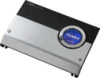
XM-2002GTR Key Features 1200W max power 200W x 2 RMS into 4 ohms, 20Hz-20kHz @ 0.1% THD 500W x 1 RMS into 4 ohms, 20Hz - 20kHz @ 0.15% THD High Level Sensing Power On 1200W max power 200W x 2 RMS into 4 ohms, 20Hz-20kHz @ 0.1% THD 500W x 1 RMS into 4 ohms, 20Hz - 20kHz @ 0.15% THD High Level Sensing Power SpeOcnifications Audio Frequency Response: 5 -...: 10 7/8 x 2 1/4 x 15 7/8" (276 x 57 x 403mm) UPC Code: 027242686717 Variable 50 - 300 Hz low pass filter 40 Hz EQ boost MOSFET output stage & power supply RCA & speaker level inputs Line level thru-put CEA-2006 Power Compliant Amplifier
XM-2002GTR Key Features 1200W max power 200W x 2 RMS into 4 ohms, 20Hz-20kHz @ 0.1% THD 500W x 1 RMS into 4 ohms, 20Hz - 20kHz @ 0.15% THD High Level Sensing Power On 1200W max power 200W x 2 RMS into 4 ohms, 20Hz-20kHz @ 0.1% THD 500W x 1 RMS into 4 ohms, 20Hz - 20kHz @ 0.15% THD High Level Sensing Power SpeOcnifications Audio Frequency Response: 5 -...: 10 7/8 x 2 1/4 x 15 7/8" (276 x 57 x 403mm) UPC Code: 027242686717 Variable 50 - 300 Hz low pass filter 40 Hz EQ boost MOSFET output stage & power supply RCA & speaker level inputs Line level thru-put CEA-2006 Power Compliant Amplifier

Service Guide
Page 1
XM-2022 US Model Canadian Model AEP Model UK Model E model AUDIO POWER SPECIFICATIONS POWER OUTPUT AND TOTAL HARMONIC DISTORTION 20 watts per channel minimum continuous average power into 4 ohms, both channels driven from 20 20,000 Hz with no...ohms) Power requirements 12 V DC car battery (negative ground) Current drain 4 A (at 4 ohms SPECIFICATIONS Rated power output 20 watts per Car Stereo Ad Hoc Committee standards. STEREO POWER AMPLIFIER SONY SERVICE MANUAL ' RR! Other Specifications Power supply system BTL (Balanced Transformer Less) circuitry Input Car stereo input (...
XM-2022 US Model Canadian Model AEP Model UK Model E model AUDIO POWER SPECIFICATIONS POWER OUTPUT AND TOTAL HARMONIC DISTORTION 20 watts per channel minimum continuous average power into 4 ohms, both channels driven from 20 20,000 Hz with no...ohms) Power requirements 12 V DC car battery (negative ground) Current drain 4 A (at 4 ohms SPECIFICATIONS Rated power output 20 watts per Car Stereo Ad Hoc Committee standards. STEREO POWER AMPLIFIER SONY SERVICE MANUAL ' RR! Other Specifications Power supply system BTL (Balanced Transformer Less) circuitry Input Car stereo input (...

Service Guide
Page 2
... vier Schraubenlocher, and bohren Sie dann die L6cher (3 mm 0). XM-2022 Mounting hoard . Fissare l'apparecchio sulla tavola con le viti in the instructions. • Do not connect any active speakers (with built- If this amplifier is extracted from the heater. • Do riot install the ... board and mark the four screw holes, then drill the holes (3 mm (1/8 in amplifiers) M the speaker cords of the left speaker. •If your car is equipped with adequate power handling capacities. Installation Before Installation •Choose the mounting location carefully so that the speaker...
... vier Schraubenlocher, and bohren Sie dann die L6cher (3 mm 0). XM-2022 Mounting hoard . Fissare l'apparecchio sulla tavola con le viti in the instructions. • Do not connect any active speakers (with built- If this amplifier is extracted from the heater. • Do riot install the ... board and mark the four screw holes, then drill the holes (3 mm (1/8 in amplifiers) M the speaker cords of the left speaker. •If your car is equipped with adequate power handling capacities. Installation Before Installation •Choose the mounting location carefully so that the speaker...

Service Guide
Page 3
...Sony dealer. • Protection circuit This amplifier is being supplied to the cassette player or tuner, check the connections. • This power amplifier employs a protection circuit' to protect the transistors and speakers if the amplifier malfunctions. Turn it mvo blu/bianco al mvo di comando a distance dello stereo... your car audio moderate so that the fins of the malfunction. Connection Example Car audio Autoradin Auto-Audioanlage Stereo per auto. POWER indicator The indicator (green) will come on when the unit is generated When a protection circuit activates, ...
...Sony dealer. • Protection circuit This amplifier is being supplied to the cassette player or tuner, check the connections. • This power amplifier employs a protection circuit' to protect the transistors and speakers if the amplifier malfunctions. Turn it mvo blu/bianco al mvo di comando a distance dello stereo... your car audio moderate so that the fins of the malfunction. Connection Example Car audio Autoradin Auto-Audioanlage Stereo per auto. POWER indicator The indicator (green) will come on when the unit is generated When a protection circuit activates, ...

Service Guide
Page 5
...Diagram: • All capacitors are in n and V4 W or less unless otherwise specified. = : B+ Line • Power voltage is seen. PRINTED WIRING BOARD -MAIN Section- 2 •Semiconductor Location Ref. Note on the side which is dc ...D303 C - 7 D304 C- 7 IC101 C - 7 IC102 B - 7 IC201 C - 6 IC202 B - 3 B Q301 B - 5 Q302 C - 4 Note on Printed Wiring Board: • o- : parts extracted from POWER/SPEAKERS Connector (+B and REM) • Voltages are in µF unless otherwise noted. tion tolerances. • Signal path. pF: 5OWV or less are not indicated except...
...Diagram: • All capacitors are in n and V4 W or less unless otherwise specified. = : B+ Line • Power voltage is seen. PRINTED WIRING BOARD -MAIN Section- 2 •Semiconductor Location Ref. Note on the side which is dc ...D303 C - 7 D304 C- 7 IC101 C - 7 IC102 B - 7 IC201 C - 6 IC202 B - 3 B Q301 B - 5 Q302 C - 4 Note on Printed Wiring Board: • o- : parts extracted from POWER/SPEAKERS Connector (+B and REM) • Voltages are in µF unless otherwise noted. tion tolerances. • Signal path. pF: 5OWV or less are not indicated except...

Service Guide
Page 6
SCHEMATIC DIAGRAM -MAIN Section- 1 2 3 4 A Tr MAI N BOARD I 5 I 6 7 8 R309 220 9 10 11 B C E CN101 O F INPUT H J K C> C25)01,2V10+1 R2121K7 5.66.2 3 2 2 13.5(IC11/20)1 6.2 1C4011V03 +I( IC101 PNRJME4A5M80PE CS21O.02V2 R2121K8 6 6 2 5 5.6 C116 4.7 0116 22K R2120K1 • C114 I 0.001 • C214 I I 0 001 R2220K1 R216 226 C216 I I4.7 10101 (2/2) 7 4 C14017V04 6.2 R1111M053 R12M03 CS22O.02V2 02221K8 3 5.66 2 813.5I0(12/021) 1 f.2 C142070V4 2 IC201 NPJMRE4SA8M0EP C2502.2V01 0221267 6 6 2 )1+ VA 4A 5 5.6 IC(221021) 1C4027V03 7 ••6.2 RW12M,...
SCHEMATIC DIAGRAM -MAIN Section- 1 2 3 4 A Tr MAI N BOARD I 5 I 6 7 8 R309 220 9 10 11 B C E CN101 O F INPUT H J K C> C25)01,2V10+1 R2121K7 5.66.2 3 2 2 13.5(IC11/20)1 6.2 1C4011V03 +I( IC101 PNRJME4A5M80PE CS21O.02V2 R2121K8 6 6 2 5 5.6 C116 4.7 0116 22K R2120K1 • C114 I 0.001 • C214 I I 0 001 R2220K1 R216 226 C216 I I4.7 10101 (2/2) 7 4 C14017V04 6.2 R1111M053 R12M03 CS22O.02V2 02221K8 3 5.66 2 813.5I0(12/021) 1 f.2 C142070V4 2 IC201 NPJMRE4SA8M0EP C2502.2V01 0221267 6 6 2 )1+ VA 4A 5 5.6 IC(221021) 1C4027V03 7 ••6.2 RW12M,...

Service Guide
Page 7
... original one. • Color Indication of Appearance Parts Example: KNOB, BALANCE (WHITE)...(RED) Parts color Cabinet's color 3-1. Description Remark 1 1-765-110-11 CORD (WITH CONNECTOR) (POWER/SPERKER) 2 7-685-645-79 SCREW +BTP 3X6 TYPE2 N-S 3 7-685-646-79 SCREW +P 3X8 TYPE2 NON-SLIT 4 3-911-058-01 SCREW *5 3-911-047-01 HEAT SINK...
... original one. • Color Indication of Appearance Parts Example: KNOB, BALANCE (WHITE)...(RED) Parts color Cabinet's color 3-1. Description Remark 1 1-765-110-11 CORD (WITH CONNECTOR) (POWER/SPERKER) 2 7-685-645-79 SCREW +BTP 3X6 TYPE2 N-S 3 7-685-646-79 SCREW +P 3X8 TYPE2 NON-SLIT 4 3-911-058-01 SCREW *5 3-911-047-01 HEAT SINK...

Service Guide
Page 8
...% 50V 20% 50V 20% 10V 20% 10V 5% 50V CN101 1-563-716-21 JACK, PIN 2P (INPUT) CN301 1-691-786-11 PIN, CONNECTOR (PC BOARD) 10P (POWER/SPEAKERS) < DIODE > C106 1-136-161-00 FILM C107 1-126-022-11 ELECT C108 1-126-022-11 ELECT C109 1-126-022-11 ELECT C110 1-124-995... 2.2uF 2.2uF 47uF 47uF 16V 20% 50V 20% 50V 20% 10V 20% 10V D301 8-719-945-59 DIODE DSA3A4 D302 8-719-048-28 LED GL8EG48 (POWER) D303 8-719-988-62 DIODE 1SS355 D304 8-719-157-23 DIODE RD4.7M-B < FUSE > F301 1-532-797-11 FUSE (BRADE TYPE) (AUTO FUSE) (7.5A/32V...
...% 50V 20% 50V 20% 10V 20% 10V 5% 50V CN101 1-563-716-21 JACK, PIN 2P (INPUT) CN301 1-691-786-11 PIN, CONNECTOR (PC BOARD) 10P (POWER/SPEAKERS) < DIODE > C106 1-136-161-00 FILM C107 1-126-022-11 ELECT C108 1-126-022-11 ELECT C109 1-126-022-11 ELECT C110 1-124-995... 2.2uF 2.2uF 47uF 47uF 16V 20% 50V 20% 50V 20% 10V 20% 10V D301 8-719-945-59 DIODE DSA3A4 D302 8-719-048-28 LED GL8EG48 (POWER) D303 8-719-988-62 DIODE 1SS355 D304 8-719-157-23 DIODE RD4.7M-B < FUSE > F301 1-532-797-11 FUSE (BRADE TYPE) (AUTO FUSE) (7.5A/32V...


